DAK-34 Power Integrations, DAK-34 Datasheet - Page 3
DAK-34
Manufacturer Part Number
DAK-34
Description
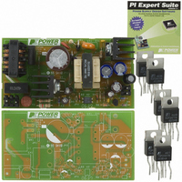
KIT DESIGN ACCELERATOR AC/DC PS
Manufacturer
Power Integrations
Series
TOPSwitch®-GXr
Specifications of DAK-34
Main Purpose
AC/DC, Primary Side
Outputs And Type
1, Isolated
Power - Output
30W
Voltage - Output
12V
Current - Output
2.5A
Voltage - Input
85 ~ 265VAC
Regulator Topology
Flyback
Frequency - Switching
132kHz
Board Type
Bare (Unpopulated) and Fully Populated
Utilized Ic / Part
TOP245
Lead Free Status / RoHS Status
Not applicable / Not applicable
Other names
596-1004


Design Idea DI-55
TOPSwitch-GX
20 W (25 W peak) DVD Supply
NTRL
Figure 1. 20 W Multiple Output DVD Supply.
LINE
Design Highlights
• Simple, low cost, low part count solution
• No heatsink required
• Low EMI-frequency jitter allows EN55022B/FCC B
• High efficiency, >75% at 90 VAC
• Low zero load power consumption, <100 mW at
• Low standby power consumption, <1 W input at 0.5 W output,
• Excellent cross-regulation
• Differential and common mode surge immunity to 3 kV
J1-2
J1-1
Application
compliance with simple EMI filter
230 VAC
230 VAC
(EN 61000-4-5)
250 VAC
275 VAC
3.15 A
RV1
F1
DVD
0.047 µF
RT1
C3
X2
t°
1N4007 x 4
TOP245P
Device
D
S
33 µF
400 V
C1
TOPSwitch-GX
CONTROL
CM Choke
TOP245P
M
5.1 kΩ
5 mH
U1
R6
L1
10 kΩ
R4
®
C
20 W (25 W pk)
Power Output
33 µF
400 V
47 µF
C4
25 V
C13
P6KE
1N3906
VR1
130
Q3
1 kΩ
1N4007GP
R7
0.1 µF
270 Ω
C16
R3
D5
68 Ω
0.01 µF
R1
1 kV
C2
1
4
www.powerint.com
www.powerint.com
2.2 nFY1
EE25L
C8
T1
12
13
10,11
8
9
UF4003
150 µF
14
35 V
7
5
D12
Input Voltage
C9
85-265 VAC
1N4148
SB540CT
SB540CT
1200 µF
1N5819
D6
10 V
C12
D11
D10
D7
18 kΩ
1/2 W
150 µF
1 Ω
R8
35 V
R2
Operation
The TOP245P selected for the design in Figure 1 is ideal for DVD and
set-top applications. The P package removes the need for a heatsink
while still delivering 20 W/25 W peak at an ambient temperature of
50 °C.
The external current limit programming and remote ON/OFF
(inhibit) functions of the M pin allow current mode control and reduced
switching frequency at light and no-load conditions. Current mode
control is implemented by R2, Q3, R3, C16, R4 and R6.
Feedback current above ~2 mA (U1 supply current) forward biases
Q3 and pulls up R6. This adjusts the sink current out of the M pin,
C6
1200 µF
10 V
C12
BEAD
L5
470 µF
47 µF
C15
25 V
25 V
C5
U2
200 Ω
TL431
R17
U3
3.3 µH
L2
180 µF
3.3 µH
3.3 µH
25 V
LTV817A
C20
0.1 µF
L3
L4
3.3 V / 5 V / 12 V / -24 V
C14
6.34 kΩ
R12
1%
10 kΩ
Output Voltage
R10
10.0 kΩ
20.0 kΩ
470 µF
1%
R11
R9
10 V
1%
C17
1.13 kΩ
20.0 kΩ
R14
R13
1%
1%
2N3906
Q5
2.0 kΩ
R16
OPTIONAL
1%
2.4 kΩ
R15
470 µF
2N3904
10 V
C18
PI-3648-080603
Q4
2SA0885
1N4005
Q1
D9
1N4005
Topology
D8
Flyback
+12 V, 500mA
-24 V, 50 mA
J2-2, 4, 5, 7
+5 V, 2.5 A
+3.3 V, 2 A
J2-3
J2-6
RET
J2-1
3
Related parts for DAK-34
Image
Part Number
Description
Manufacturer
Datasheet
Request
R

Part Number:
Description:
KIT DESIGN ACCELERATOR MODEM
Manufacturer:
Power Integrations
Datasheet:

Part Number:
Description:
KIT DESIGN ACCELERATOR SET TOP
Manufacturer:
Power Integrations
Datasheet:

Part Number:
Description:
KIT REF DES DPA 6.6W DC-DC CONV
Manufacturer:
Power Integrations
Datasheet:

Part Number:
Description:
KIT DESIGN ACCELERATOR POE CONV
Manufacturer:
Power Integrations
Datasheet:

Part Number:
Description:
DESIGN ACCELERATOR KIT XT SWITCH
Manufacturer:
Power Integrations
Datasheet:

Part Number:
Description:
DESIGN ACCELERATOR KIT LP SWITCH
Manufacturer:
Power Integrations
Datasheet:

Part Number:
Description:
KIT DESIGN ACC PEAKSWITCH FAMILY
Manufacturer:
Power Integrations
Datasheet:

Part Number:
Description:
KIT DESIGN ACCELERATOR ADAPTER
Manufacturer:
Power Integrations
Datasheet:

Part Number:
Description:
KIT DESIGN ACCELERATOR ADAPTER
Manufacturer:
Power Integrations
Datasheet:

Part Number:
Description:
KIT DESIGN ACCELERATOR DC-DC
Manufacturer:
Power Integrations
Datasheet:
