DAK-34 Power Integrations, DAK-34 Datasheet
DAK-34
Specifications of DAK-34


Related parts for DAK-34


DAK-34 Summary of contents
Page 1
... The products and applications illustrated herein (including circuits external to the products and transformer construction) may be covered by one or more U.S. and foreign patents or potentially by pending U.S. and foreign patent applications assigned to Power Integrations. A complete list of Power Integrations’ patents may be found at www.powerint.com. ...
Page 2
... Common Mode Surge, 1.2/50 Differential Mode Surge, 1.2/50 µs ....................................................................26 14.2 14.3 Common Mode, 100 kHz Ring Wave ................................................................26 14.4 Differential Mode, 100 kHz Ring Wave..............................................................26 15 Revision History ....................................................................................................27 Power Integrations Tel: +1 408 414 9200 Fax: +1 408 414 9201 www.powerint.com Table Of Contents µs .......................................................................25 Page ...
Page 3
... Although the EP-34 is designed to satisfy safety isolation requirements, the engineering prototype has not been agency approved. Therefore, all testing should be performed using an isolation transformer to provide the AC input to the prototype board. Page Power Integrations Tel: +1 408 414 9200 Fax: +1 408 414 9201 www.powerint.com ...
Page 4
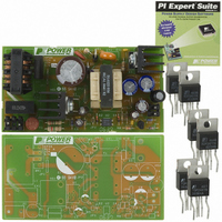
... TOPSwitch-GX. The document contains the power supply specification, schematic, bill of materials, transformer documentation, printed circuit board layout, and performance data. Power Integrations Tel: +1 408 414 9200 Fax: +1 408 414 9201 www.powerint.com Figure 1 – EP-34 Populated Circuit Board. ...
Page 5
... W), 25 OUT Meets CISPR22B / EN55022B Designed to meet IEC950, UL1950 Class II 1.2/50 µs surge, IEC 1000-4- Ω series impedance, differential common mode 100 kHz ring wave, 500 A short kV circuit current, differential and common mode o C Free convection, sea level Power Integrations www.powerint.com C ...
Page 6
... Schematic Power Integrations Tel: +1 408 414 9200 Fax: +1 408 414 9201 www.powerint.com Figure 2 – EP-34 Schematic. Page ...
Page 7
... R6 to provide feedback information to the U1 CONTROL pin. The optocoupler output also provides power to U1 from the bias winding during normal operating conditions. Diode D4 and capacitor C10 apply drive to the optocoupler during supply Page Power Integrations Tel: +1 408 414 9200 Fax: +1 408 414 9201 www.powerint.com ...
Page 8
... Capacitor C3 rolls off the gain relatively low frequency. Resistor R5 provides a zero to cancel the phase shift of C5. Resistor R6 sets the gain of the direct signal path from the supply output through U2 and U3. Components C9 and R8 roll off the gain of U3. Power Integrations Tel: +1 408 414 9200 Fax: +1 408 414 9201 www.powerint.com Page ...
Page 9
... PCB Layout Figure 3 – EP-34 Printed Circuit Board Layout (dimensions 0.001”). Page Power Integrations Tel: +1 408 414 9200 Fax: +1 408 414 9201 www.powerint.com ...
Page 10
... Header 0.156” spacing, 3 pos 26-48-1031 (pull middle pin) Header 26-48-1021 0.156” spacing, 2 pos EP-34 Printed Circuit Board, Rev. A Tinned Bus Wire, 22 AWG Manufacturer Power Integrations Isocom National Semiconductor On Semiconductor General Semiconductor General Semiconductor Any General Semiconductor Panasonic Vishay United Chemicon ...
Page 11
... VRMS Pins 1-3, all other windings open Pins 1-3, with Pins 6-10 shorted, measured at 100 kHz, 0.4 VRMS Description Tel: +1 408 414 9200 Fax: +1 408 414 9201 3000 VAC 827 µ H, ± 10% 750 kHz (Min.) 20 µ H (Max.) Power Integrations www.powerint.com 2 ...
Page 12
... Varnish impregnate (item [8]). 7.6 Transformer Sources For information on the vendors used to source the transformers used on this board, please visit the Power Integrations' Web site at the URL below and select “Engineering Prototype Boards”. http://www.powerint.com/componentsuppliers.htm Power Integrations Tel: +1 408 414 9200 Fax: +1 408 414 9201 www ...
Page 13
... Output Winding Diode Forward Voltage Drop 51 39 Output Rectifier Maximum Peak Inverse Voltage 9.17 0.04 Peak Secondary Current 4.52 0.02 Secondary RMS Current 3.77 0.02 Output Capacitor RMS Ripple Current Tel: +1 408 414 9200 Fax: +1 408 414 9201 Power Integrations www.powerint.com ...
Page 14
... Rounded Down NSx Rounded Down Volts Vox Rounded Up NSx Rounded Up Volts Vox AWGSx Range AWG Power Integrations Tel: +1 408 414 9200 Fax: +1 408 414 9201 www.powerint.com Core and Bobbin Type Core Manufacturing Bobbin Manufacturing 827 Primary Inductance 58 Primary Winding Number of Turns 7 ...
Page 15
... Figure 7 - Zero Load Input Power vs. Input Line Voltage, Room Temperature, 60 Hz. Page Iout = 2.5 A Iout = 1 A 120 140 160 180 200 220 AC Input Voltage 145 165 185 AC Input Voltage Tel: +1 408 414 9200 Fax: +1 408 414 9201 240 260 280 205 225 245 265 Power Integrations www.powerint.com ...
Page 16
... Figure 9 – EP-34 Line Regulation, Room Temperature, Full Load. Power Integrations Tel: +1 408 414 9200 Fax: +1 408 414 9201 www.powerint.com EP-34 Load Regulation 1 2 Output Load (A) AC Input Voltage ...
Page 17
... Figure 10 – EP-34 Overload Power vs. Line Voltage, Room Temperature. Page Overload Power vs Line Voltage 140 160 180 Input Voltage (VAC) Tel: +1 408 414 9200 Fax: +1 408 414 9201 200 220 240 260 Power Integrations www.powerint.com 280 ...
Page 18
... Item Ambient Balun (L1) Bridge (BR1) Transformer (T1) Clamp Zener (VR1) TOPSwitch (U1) Rectifier (D3) Figure 11 - Infrared Thermograph of EP-34, 85 VAC Input, Maximum Continuous Load, 22 °C Ambient. Power Integrations Tel: +1 408 414 9200 Fax: +1 408 414 9201 www.powerint.com Temperature (°C) 85 115 230 85 115 VAC ...
Page 19
... A /div. DRAIN , 200 V, 2 µ s/div. Lower: V DRAIN Figure 15 - Start-up Profile, 230 VAC ms/div. Figure 17 - 265 VAC Input and Maximum Load. Upper 0.5 A /div. DRAIN Lower 200 V, 1 ms/div. DRAIN Power Integrations Tel: +1 408 414 9200 Fax: +1 408 414 9201 www.powerint.com ...
Page 20
... Figure 18 – EP-34 Transient Response, 115 VAC, 75%-100%-75% Load Step. Top: Load Current, 1 A/div. Bottom: Output Voltage. 50 mV, 500 µ s/div. Power Integrations Tel: +1 408 414 9200 Fax: +1 408 414 9201 www.powerint.com Figure 19 – EP-34 Transient Response, 230 VAC, 75%-100%-75% Load Step Upper: Load Current, 1 A/div ...
Page 21
... Figure 20 - Oscilloscope Probe Prepared for Ripple Measurement (End Cap and Ground Lead Removed). Figure 21 - Oscilloscope Probe with Probe Master 5125BA BNC Adapter (Modified with wires for probe ground for ripple measurement, and two parallel decoupling capacitors added). Page Probe Ground Probe Tip Power Integrations Tel: +1 408 414 9200 Fax: +1 408 414 9201 www.powerint.com ...
Page 22
... Measurement Results Figure 22 - Ripple, 85 VAC, Full Load div. Figure 24 - Ripple, 230 VAC, Full Load /div. Power Integrations Tel: +1 408 414 9200 Fax: +1 408 414 9201 www.powerint.com Figure Ripple, 115 VAC, Full Load div. Page ...
Page 23
... Crossover Frequency = 1.16 kHz Phase Margin = 66.5 ° 12.2 230 VAC Maximum Load Figure 26 - Gain-Phase Plot, 230 VAC, Maximum Steady State Load. Vertical Scale: Gain = 10 dB/div, Phase = 50°/div. Crossover Frequency = 831 Hz, Phase Margin = 79.4 ° Page Power Integrations Tel: +1 408 414 9200 Fax: +1 408 414 9201 www.powerint.com ...
Page 24
... Conducted EMI Figure 26 - Conducted EMI, Maximum Steady State Load, 115 VAC, 60 Hz, and EN55022 B Limits. Figure 27 - Conducted EMI, Maximum Steady State Load, 230 VAC, 60 Hz, and EN55022 B Limits. Power Integrations Tel: +1 408 414 9200 Fax: +1 408 414 9201 www.powerint.com Page ...
Page 25
... Tel: +1 408 414 9200 Fax: +1 408 414 9201 Test Result PASS PASS PASS PASS PASS PASS PASS PASS PASS PASS (1 power interruption/10strikes, recovered) PASS (2 power interruptions/10 strikes, recovered) PASS (4 power interruptions/10 strikes, recovered) Power Integrations www.powerint.com ...
Page 26
... Differential Mode, 100 kHz Ring Wave Surge Phase Angle (°) Voltage 270 270 270 270 Power Integrations Tel: +1 408 414 9200 Fax: +1 408 414 9201 www.powerint.com µ s Generator Number of Impedance Strikes 12 Ω Ω Ω Ω Ω Ω Ω Ω Ω Ω ...
Page 27
... Revision Description & changes 0.1 First draft 0.2 Second draft 0.3 Third draft 1.0 First Release 1.1 Second Release – Transformer specification on page 11 corrected (primary inductance, resonant frequency and ALG). Tel: +1 408 414 9200 Fax: +1 408 414 9201 Power Integrations www.powerint.com ...
Page 28
... For the latest updates, visit our Web site: www.powerint.com Power Integrations may make changes to its products at any time. Power Integrations has no liability arising from your use of any information, device or circuit described herein nor does it convey any license under its patent rights or the rights of others ...