DAK-34 Power Integrations, DAK-34 Datasheet - Page 2
DAK-34
Manufacturer Part Number
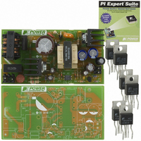
DAK-34
Description
KIT DESIGN ACCELERATOR AC/DC PS
Manufacturer
Power Integrations
Series
TOPSwitch®-GXr
Specifications of DAK-34
Main Purpose
AC/DC, Primary Side
Outputs And Type
1, Isolated
Power - Output
30W
Voltage - Output
12V
Current - Output
2.5A
Voltage - Input
85 ~ 265VAC
Regulator Topology
Flyback
Frequency - Switching
132kHz
Board Type
Bare (Unpopulated) and Fully Populated
Utilized Ic / Part
TOP245
Lead Free Status / RoHS Status
Not applicable / Not applicable
Other names
596-1004


1
2
3
4
5
6
7
8
9
10
11
12
13
14
15
4.1
4.2
4.3
4.4
7.1
7.2
7.3
7.4
7.5
7.6
9.1
9.2
9.3
9.4
11.1
11.2
11.3
11.4
11.5
12.1
12.2
14.1
14.2
14.3
14.4
Introduction.................................................................................................................4
Power Supply Specification ........................................................................................5
Schematic...................................................................................................................6
Circuit Description ......................................................................................................7
PCB Layout ................................................................................................................9
Bill Of Materials ........................................................................................................10
Transformer Specification.........................................................................................11
Transformer Spreadsheets .......................................................................................13
Performance Data ....................................................................................................15
9.3.1
9.3.2
11.5.1
11.5.2
Thermal Performance ...........................................................................................18
Waveforms............................................................................................................19
Control Loop Measurements.................................................................................23
Conducted EMI .....................................................................................................24
AC Surge and 100 kHz Ring Wave Immunity .......................................................25
Revision History ....................................................................................................27
Input EMI Filtering ...............................................................................................7
TOPSwitch Primary .............................................................................................7
Output Rectification .............................................................................................7
Output Feedback.................................................................................................7
Electrical Diagram .............................................................................................11
Electrical Specifications.....................................................................................11
Materials............................................................................................................11
Transformer Build Diagram ...............................................................................12
Transformer Construction..................................................................................12
Transformer Sources.........................................................................................12
Efficiency ...........................................................................................................15
No-load Input Power..........................................................................................15
Regulation .........................................................................................................16
Overload Power.................................................................................................17
Drain Voltage and Current, Normal Operation...................................................19
Output Voltage Start-up Profile..........................................................................19
Drain Voltage and Current Start-up Profile ........................................................19
Load Transient Response (75% to 100% Load Step) .......................................20
Output Ripple Measurements............................................................................21
115 VAC Maximum Load...................................................................................23
230 VAC Maximum Load...................................................................................23
Common Mode Surge, 1.2/50
Differential Mode Surge, 1.2/50 µs ....................................................................26
Common Mode, 100 kHz Ring Wave ................................................................26
Differential Mode, 100 kHz Ring Wave..............................................................26
Power Integrations
Tel: +1 408 414 9200 Fax: +1 408 414 9201
www.powerint.com
Load ...........................................................................................................16
Line ............................................................................................................16
Ripple Measurement Technique ................................................................21
Measurement Results ................................................................................22
Table Of Contents
µs
.......................................................................25
Page 2 of 28
Related parts for DAK-34
Image
Part Number
Description
Manufacturer
Datasheet
Request
R

Part Number:
Description:
KIT DESIGN ACCELERATOR MODEM
Manufacturer:
Power Integrations
Datasheet:

Part Number:
Description:
KIT DESIGN ACCELERATOR SET TOP
Manufacturer:
Power Integrations
Datasheet:

Part Number:
Description:
KIT REF DES DPA 6.6W DC-DC CONV
Manufacturer:
Power Integrations
Datasheet:

Part Number:
Description:
KIT DESIGN ACCELERATOR POE CONV
Manufacturer:
Power Integrations
Datasheet:

Part Number:
Description:
DESIGN ACCELERATOR KIT XT SWITCH
Manufacturer:
Power Integrations
Datasheet:

Part Number:
Description:
DESIGN ACCELERATOR KIT LP SWITCH
Manufacturer:
Power Integrations
Datasheet:

Part Number:
Description:
KIT DESIGN ACC PEAKSWITCH FAMILY
Manufacturer:
Power Integrations
Datasheet:

Part Number:
Description:
KIT DESIGN ACCELERATOR ADAPTER
Manufacturer:
Power Integrations
Datasheet:

Part Number:
Description:
KIT DESIGN ACCELERATOR ADAPTER
Manufacturer:
Power Integrations
Datasheet:

Part Number:
Description:
KIT DESIGN ACCELERATOR DC-DC
Manufacturer:
Power Integrations
Datasheet:
