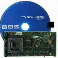
ATSTK503 Atmel, ATSTK503 Datasheet - Page 13

ATSTK503
Manufacturer Part Number
ATSTK503
Description
STARTER KIT AVR EXP MODULE 100P
Manufacturer
Atmel
Datasheet
1.ATSTK503.pdf
(17 pages)
Specifications of ATSTK503
Accessory Type
STK500 Expansion Module
Processor To Be Evaluated
Atmegaxxxx
Data Bus Width
8 bit
Interface Type
JTAG
For Use With/related Products
100-pin megaAVR Devices
For Use With
ATSTK500 - PROGRAMMER AVR STARTER KIT
Lead Free Status / RoHS Status
Lead free / RoHS Compliant
RS-232 Driver
The STK503 has an RS-232 driver operating at target voltages from 1.8 to 5.5V
with a maximum speed of 480kbps. There are two transmit and two receive pins.
With the RS-232 port available on STK500, you have three channels available for
your design.
The driver pins are available on the connector in the lower right corner of the
STK503 (see figure 7-1 and 7-2).
Figure 7-1: The RS-232 connector
To use the driver you must connect the logic level pins to the AVR and the RS-
232 pins to the external device. The connector is marked with AVR and RS-232,
where the pins on the AVR side must be connected to the RxD and TxD pins on
the AVR, and RS-232 side connects to a connector or your RS-232-enabled
device. The arrows show the signal directions.
Figure 7-2: RS-232 connection
As the STK503 has no 9-pin or 25-pin connector, you must make your own
connection. You can however decide if you will use only TxD/RxD lines, giving
you two channels, or if handshake signals like RTS/CTS or DTR/DSR will be
used. In the latter case, you must connect the handshake signals to regular
PORT pins that are controlled by software.
13


