ATSTK503 Atmel, ATSTK503 Datasheet - Page 10

ATSTK503
Manufacturer Part Number
ATSTK503
Description
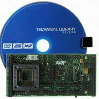
STARTER KIT AVR EXP MODULE 100P
Manufacturer
Atmel
Datasheet
1.ATSTK503.pdf
(17 pages)
Specifications of ATSTK503
Accessory Type
STK500 Expansion Module
Processor To Be Evaluated
Atmegaxxxx
Data Bus Width
8 bit
Interface Type
JTAG
For Use With/related Products
100-pin megaAVR Devices
For Use With
ATSTK500 - PROGRAMMER AVR STARTER KIT
Lead Free Status / RoHS Status
Lead free / RoHS Compliant
You are now ready to program the device. For more information on how to use
the programming dialog, see the Frontend software section in the STK500 user
guide.
STK503 Clock Sources
The ATmega2560 and its like have two clock inputs; XTAL and TOSC. Two
switches on the STK503 selects what is connected to these two inputs.
Figure 5-1: The clock selection switches XTAL and TOSC
The XTAL switch
A clock source connected to the XTAL clock input is used to drive the internal
chip clock. The source can be a crystal, a resonator or an external clock signal.
The XTAL switch sitting on STK503 selects what is connected to the XTAL pins.
STK500 can supply two different clock signals:
You select between these two sources with the OSCSEL jumper. This signal is
available on STK503.
The STK503 also has a socket for a crystal. This socket should be used instead
of the one on STK500, at least for high-frequency crystals (>8MHz).
The XTAL switch selects what signal is routed to the XTAL pin on the AVR:
6.
•
•
•
•
Start AVR Studio. On the Tools menu, select "Program AVR/ Connect..."
STK500 can generate a software controlled signal with a maximum
frequency of 3.69MHz
A crystal can be placed in the crystal socket.
The STK500 supplied clock (set the switch to the position indicated by the
text STK500)
The crystal socket on STK503 (set the switch to the position nearest the
crystal socket)
10


