TC642EV Microchip Technology, TC642EV Datasheet - Page 9
TC642EV
Manufacturer Part Number
TC642EV
Description
KIT EVALUATION FOR TC642
Manufacturer
Microchip Technology
Specifications of TC642EV
Processor To Be Evaluated
TC642 and TC646
Lead Free Status / RoHS Status
Lead free / RoHS Compliant
Lead Free Status / RoHS Status
Lead free / RoHS Compliant, Lead free / RoHS Compliant
Other names
Q698359


5.0
Designing with the TC642 involves the following:
(1) The temp sensor network must be configured to
(2) The minimum fan speed (V
(3) The output drive transistor and associated circuitry
(4) The SENSE network, R
(5) If shutdown capability is desired, the drive require-
FIGURE 5-1:
5.1
The temperature signal connected to V
voltage in the range of 1.25V to 2.65V (typical) for 0%
to 100% of the temperature range of interest. The
circuit in Figure 5-2 illustrates a convenient way to
provide this signal.
Figure 5-2 shows a simple temperature dependent
voltage divider circuit. RT
mistor while R
ply voltage, V
combination of RT
lel combination of RT
R
temperatures is obtained from the manufacturer’s
specifications. Thermistors are often referred to in
terms of their resistance at 25°C.
TEMP
2002 Microchip Technology Inc.
deliver 1.25V to 2.65V on V
temperature range to be regulated.
must be selected.
be designed for maximum efficiency, while
delivering adequate signal amplitude.
ments of the external signal or circuit must be
considered.
). The resistance of the thermistor at various
Temperature Sensor Design
Shutdown
TYPICAL APPLICATIONS
Note: *See cautions regarding latch-up considerations in Section 5.0, "Typical Applications".
DD
1
and R
, is divided between R
1
and R
2
(Optional)
1
Typical Application Circuit.
are standard resistors. The sup-
and R
1
1
is a conventional NTC ther-
(for convenience, the paral-
SENSE
1
IN
MIN
will be referred to as
for 0% to 100% of the
+5V*
) must be set.
and C
R
R
2
IN
1
2
and the parallel
R
R
must output a
4
3
SENSE
C
0.01 µF
C
0.01 µF
B
B
NTC
C
1 µF
, must
F
1
3
2
V
V
C
MIN
F
IN
8
V
DD
TC642
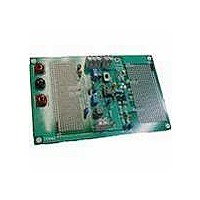
The TC642 demonstration and prototyping board
(TC642DEMO), and
(TC642EV), provide working examples of TC642 cir-
cuits and prototyping aids. The TC642DEMO is a
printed circuit board optimized for small size and ease
of inclusion into system prototypes. The TC642EV is a
larger board intended for benchtop development and
analysis. At the very least, anyone contemplating a
design using the TC642 should consult the documen-
tation for both TC642EV (DS21403) and TC642DEMO
(DS21401).
GND
C
1 µF
4
B
SENSE
FAULT
V
OUT
6
7
5
Thermal
Shutdown
the
C
SENSE
R
TC642
BASE
R
SENSE
DS21444C-page 9
TC642
Evaluation
+12V
Fan
Q
1
Kit
Related parts for TC642EV
Image
Part Number
Description
Manufacturer
Datasheet
Request
R

Part Number:
Description:
DEMO BOARD FOR TC642/46/47/48/49
Manufacturer:
Microchip Technology
Datasheet:

Part Number:
Description:
Manufacturer:
Microchip Technology Inc.
Datasheet:
Part Number:
Description:
Manufacturer:
Microchip Technology Inc.
Datasheet:
Part Number:
Description:
Manufacturer:
Microchip Technology Inc.
Datasheet:
Part Number:
Description:
Manufacturer:
Microchip Technology Inc.
Datasheet:
Part Number:
Description:
Manufacturer:
Microchip Technology Inc.
Datasheet:
Part Number:
Description:
Manufacturer:
Microchip Technology Inc.
Datasheet:
Part Number:
Description:
Manufacturer:
Microchip Technology Inc.
Datasheet:
Part Number:
Description:
Manufacturer:
Microchip Technology Inc.
Datasheet: