TC642EV Microchip Technology, TC642EV Datasheet - Page 15
TC642EV
Manufacturer Part Number
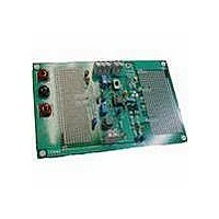
TC642EV
Description
KIT EVALUATION FOR TC642
Manufacturer
Microchip Technology
Specifications of TC642EV
Processor To Be Evaluated
TC642 and TC646
Lead Free Status / RoHS Status
Lead free / RoHS Compliant
Lead Free Status / RoHS Status
Lead free / RoHS Compliant, Lead free / RoHS Compliant
Other names
Q698359


5.7
Noise present on the V
erroneous operation of the FAULT output. As a result,
these inputs should be bypassed with a 0.01 F
capacitor mounted as close to the package as is possi-
ble. This is particularly true of V
driven from a high impedance source (such as a ther-
mistor). In addition, the V
with a 1 µF capacitor. Grounds should be kept as short
as possible. To keep fan noise off the TC642 ground
pin, individual ground returns for the TC642 and the low
side of the fan current sense resistor should be used.
FIGURE 5-9:
2002 Microchip Technology Inc.
Shutdown
Fan
Power Supply Routing and
Bypassing
(Optional)
10 k
R
8
Design Example.
IN
DD
and V
input should be bypassed
+5V
Q
2
MIN
20.5 k
3.83 k
IN
+5V
R
R
, which is usually
1
2
inputs may cause
R
18 k
R5
33 k
6
C
0.01 F
C
0.01 µF
@ 25˚C
10 k
B
B
C
1 F
NTC
1
1
3
2
C
V
V
1 F
F
MIN
IN
C
B
+
+5V
V
DD
TC642
8
Design Example
Step 1. Calculate R
Step 2. Set minimum fan speed V
Step 3. Design the output circuit.
GND
4
having a resistance of 10 k
and 4.65 k
R
Q
R
SENSE
R
Limit the divider current to 100 µA from which
R
Maximum fan motor current = 250 mA.
FAULT
V
2
7
1
1
5
OUT
= 3.83 k
= 800 .
= 20.5 k
= 33 k
beta is chosen at 50 from which
6
7
5
1
and R
Thermal Fault
at T
and R
C
0.1 F
Fan/
MAX
SENSE
6
2
= 18 k
based on using an NTC
(45°C) (see Figure 5-9).
MIN
DS21444C-page 15
800
TC642
R
= 1.8V.
7
at T
+12V
Fan
MIN
Q
R
1
SENSE
2.2
(25°C)
Related parts for TC642EV
Image
Part Number
Description
Manufacturer
Datasheet
Request
R

Part Number:
Description:
DEMO BOARD FOR TC642/46/47/48/49
Manufacturer:
Microchip Technology
Datasheet:

Part Number:
Description:
Manufacturer:
Microchip Technology Inc.
Datasheet:
Part Number:
Description:
Manufacturer:
Microchip Technology Inc.
Datasheet:
Part Number:
Description:
Manufacturer:
Microchip Technology Inc.
Datasheet:
Part Number:
Description:
Manufacturer:
Microchip Technology Inc.
Datasheet:
Part Number:
Description:
Manufacturer:
Microchip Technology Inc.
Datasheet:
Part Number:
Description:
Manufacturer:
Microchip Technology Inc.
Datasheet:
Part Number:
Description:
Manufacturer:
Microchip Technology Inc.
Datasheet:
Part Number:
Description:
Manufacturer:
Microchip Technology Inc.
Datasheet: