NLSF595EVB ON Semiconductor, NLSF595EVB Datasheet
NLSF595EVB
Specifications of NLSF595EVB
NLSF595EVBOS


Related parts for NLSF595EVB


NLSF595EVB Summary of contents
Page 1
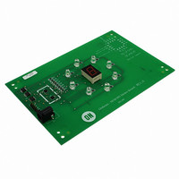
NLSF595 Serial (SPI) Tri−Color LED Driver The NLSF595 is advanced CMOS shift register with open drain outputs fabricated with 0.6 mm silicon gate CMOS technology. This device is used in conjunction with a microcontroller, with only one dedicated line. All ...
Page 2
VCC RCK SCK SCLR GND 8 9 SQH Figure 1. Pin Assignment (TSSOP−16 ...
Page 3
OE RCK D SI SRA R D SRB R D SRC R D SRD R D SRE R D SRF R D SRG R D SRH SCK R SCLR NLSF595 STRA STRB Q D ...
Page 4
MAXIMUM RATINGS Symbol V Positive DC Supply Voltage CC V Digital Input Voltage Output Voltage OUT I Input Diode Current IK I Output Diode Current Output Current, per Pin OUT I DC Supply Current, ...
Page 5
DC ELECTRICAL CHARACTERISTICS Î Î Î Î ...
Page 6
AC ELECTRICAL CHARACTERISTICS Î Î Î Î ...
Page 7
TIMING REQUIREMENTS (Input t Î Î Î Î Î Î Î Î Î Î Î Î Î Î Î Î Î Î Î Î Î Î Î Î Î Î Î Î Î Î Î Î Î Î Symbol Parameter ...
Page 8
NLSF595 OE 2.7 V NLSF595 Data SI I/O or SPI Clock (MISO) SCK EN RCK MCU NLSF595 RCK ...
Page 9
SCK 50 1/f max t t PLH PHL SQH 50 Figure 6. RCK 50 PLZ PZL QA−QH V +0 Figure 8. SCLR 50% VALID 50 ...
Page 10
SCK SI SCLR RCK SQH NOTE: output high−impedance state. INPUT Figure 15. Input Equivalent Circuit NLSF595 Figure 14. Timing Diagram http://onsemi.com 10 ...
Page 11
QA ON LED 0 DATA Data Duty Cycle Not Important Clock 250 ns For Cascading Devices Data Clock EN NLSF595 OFF OFF OFF See Data Sheet for Pinout ...
Page 12
ORDERING INFORMATION Circuit Device Order Indicator Number Technology NLSF595MNR2 NL NLSF595MNR2G NL NLSF595DTR2 NL †For information on tape and reel specifications, including part orientation and tape sizes, please refer to our Tape and Reel Packaging Specifications Brochure, BRD8011/D. *This package ...
Page 13
... C NOTE 3 SOLDERING FOOTPRINT* 0.575 0.022 3.25 0.128 *For additional information on our Pb−Free strategy and soldering details, please download the ON Semiconductor Soldering and Mounting Techniques Reference Manual, SOLDERRM/D. NLSF595 QFN−16 MN SUFFIX CASE 485G−01 ISSUE B NOTES: 1. DIMENSIONING AND TOLERANCING PER ASME Y14 ...
Page 14
... N F DETAIL E DETAIL American Technical Support: 800−282−9855 Toll Free USA/Canada Japan: ON Semiconductor, Japan Customer Focus Center 2−9−1 Kamimeguro, Meguro−ku, Tokyo, Japan 153−0051 Phone: 81−3−5773−3850 http://onsemi.com 14 NOTES: 1. DIMENSIONING AND TOLERANCING PER ANSI Y14.5M, 1982. ...