CBC5300-24C Cymbet Corporation, CBC5300-24C Datasheet - Page 7
CBC5300-24C
Manufacturer Part Number
CBC5300-24C
Description
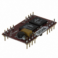
ENERCHIP EH CBC5300 MODULE
Manufacturer
Cymbet Corporation
Series
EnerChip™ EHr
Type
Energy Harvestingr
Datasheet
1.CBC5300-24C.pdf
(11 pages)
Specifications of CBC5300-24C
Module/board Type
Energy Harvesting Module
Input Voltage
0.25 V to 4 V
Output Voltage
3.6 V
Board Size
30.5 mm x 17.2 mm
Maximum Operating Temperature
+ 70 C
Minimum Operating Temperature
0 C
Product
Power Management Modules
Dimensions
30.5 mm x 17.2 mm
Lead Free Status / RoHS Status
Request inventory verification / Request inventory verification
For Use With/related Products
Thin Film Rechargeable Solid State Battery
Lead Free Status / Rohs Status
Lead free / RoHS Compliant
Other names
859-1000-5


Preliminary
As configured, the CBC5300 will operate with many transducer types. However, performance specifications
of transducers - namely output impedance - will affect the power conversion efficiency of the CBC5300 kit as
designed. Please contact Cymbet Applications Engineering at the phone number shown below to discuss your
specific application and desired transducer(s).
The CBC5300 module is designed to work with transducers having an output impedance over the range of 58Ω
to 4kΩ and an input voltage range of 270mV to 1.5V. The minimum open circuit voltage to start operation is
700mV. Peak efficiency will occur at a nominal transducer input voltage of 800mV to 1.0V at 1kΩ. Operating
characteristics for most transducer types are typically available from the manufacturer’s data sheet. An
example photovoltaic cell operating curve is shown below. Output impedance, operating voltage, and peak
power point can also be verified by empirical measurements. To do this, measure the load voltage and current
as a variable load impedance across the transducer is swept over a broad enough range where the peak power
point can be found by finding the maximum product of the measured load voltage and current.
To configure the CBC5300 to work with a given transducer, the optimal transducer operating voltage point
must first be obtained though the manufacturer’s data sheet or from empirical measurements. Next calculate
the values needed for a voltage divider to set the operating voltage point on the V
of the voltage divider shown in Figure 3 uses V
divider is connected to ground. V
R2 (bottom resistor) is in the range of 500kΩ to 1MΩ with the optimal value around 750kΩ. Note: Better
circuit performance (i.e., less input ripple voltage) will be obtained if R2 is made smaller than 750kΩ. A more
useful formula is: R1 = R2 * ((V
1.01V, R1 can be determined as R1 = 1MΩ * ((4.06V / 1.01V) - 1) = 3.02MΩ. A 3.01MΩ resistor is the nearest
standard value. R2 was chosen as a standard resistor value. 750kΩ for R2 is also a standard resistor value but
the V
Capacitor C1 (47µF) is used to set the bandwidth of the boost converter control loop. If a low impedance
transducer is used the value of C1 might have to be reduced in value. This can be verified using an oscilloscope
to check the waveform on GATE (pin 3). The waveform should be three pulses followed by a longer interval,
followed again by three pulses. The three pulses will have approximately 16.7µs of high duration followed by
16.7µs of low duration. If more than three pulses are in the waveform then the value of C1 should be reduced
to obtain the nominal waveform.
Setting the Under Voltage Lockout Voltage
The under voltage lockout (UVLO SEL) voltage should be set at or above the operating point, V
prevent the EnerChip from inadvertently powering the boost converter when insufficient input transducer power
is available. Normally, UVLO should be set to a value that is 20% to 80% above V
adding one or more series diodes between UVLO SEL and V
700mV; to raise it to 1.4V, insert one standard silicon diode. To reach intermediate voltages, Schottky diodes
may be used.
DS-72-06 Rev06
OPER
voltage will be further away from nominal due to the standard resistor values available for R1.
©2009 Cymbet Corporation • Tel: +1-763-633-1780 • www.cymbet.com
REG
OPER
/ V
is equal to V
Current-Voltage Curve
OPER
) - 1). Example: For a 1kΩ photovoltaic cell with operating voltage of
REG
REG
(pin 11) as its voltage source; the bottom of the voltage
* (R2 / (R1 + R2)), where V
IN.
For example, the nominal voltage at UVLO SEL is
V
I
V
I
P
SC
OP
OC
OP
MAX
: Short-circuit current
: Optimum operating current
: Open-circuit voltage
: Optimum operating voltage
: Maximum operating power
EnerChip EH CBC5300
OPER.
OPER
REG
is nominally 4.06V and
UVLO SEL can be set by
pin (pin 10). The top
OPER,
in order to
Page 7 of 11
Related parts for CBC5300-24C
Image
Part Number
Description
Manufacturer
Datasheet
Request
R


Part Number:
Description:
ENERCHIP CC EVAL KIT
Manufacturer:
Cymbet Corporation
Datasheet:

Part Number:
Description:
ENERCHIP CC SEH EVAL KIT
Manufacturer:
Cymbet Corporation
Datasheet:

Part Number:
Description:
ENERCHIP EP ENERGY HARVEST EVAL
Manufacturer:
Cymbet Corporation
Datasheet: