CBC5300-24C Cymbet Corporation, CBC5300-24C Datasheet
CBC5300-24C
Specifications of CBC5300-24C


Related parts for CBC5300-24C


CBC5300-24C Summary of contents
Page 1
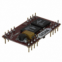
... EnerChips when it is necessary to conserve - Active RFID battery life in prolonged low input power conditions. The EnerChip EH CBC5300 as shown in Figure 2 has - two CBC050 50µAh EnerChip rechargeable battery cells, for a total 100µAh of capacity. Preliminary ...
Page 2
... Same potential as system ground. Tie to GND. Output signal used for setting operating point. Leave unconnected or use as a test point. Active low output from the CBC5300 indicating that the EnerChips have been charged or are being charged. This is an open drain output with an internal 10MΩ pull-up resistor to V Recommendations to Save Power for additional information ...
Page 3
... DIP Module Connecting the CBC5300 to the System The CBC5300 board has two control lines that can be connected to a microcontroller (MCU) for the purpose of conserving available energy, using incoming power efficiently, and extending EnerChip battery life. The table below describes the functionality of the connector pins. ...
Page 4
... For design guidelines in selecting an external boost capacitor, see the section titled Designing for Pulse Discharge Cur- rents in Wireless Devices. Application Overview The following sections provide design guidance and system level considerations for optimizing the performance and service life of the CBC5300. Specifications subject to change without notice. ©2009 Cymbet Corporation • Tel: +1-763-633-1780 • www.cymbet.com DS-72-06 Rev06 ...
Page 5
... Once the capacitance has been determined, the capacitor charging time can be calculated using the following formula: Charge formula Vmin / Vmax)] where capacitor charging time, from Vmin to Vmax R = battery resistance C = output capacitance, in parallel with battery ©2009 Cymbet Corporation • Tel: +1-763-633-1780 • www.cymbet.com DS-72-06 Rev06 EnerChip EH CBC5300 Page ...
Page 6
... That amount of charge is transferred from the EnerChips into the output capacitor, which then delivers the charge to the load at the rate demanded by the radio. On the CBC5300, there is a series diode between the output capacitor and the output pin (V In that scenario, 50% of the 100µ ...
Page 7
... Preliminary As configured, the CBC5300 will operate with many transducer types. However, performance specifications of transducers - namely output impedance - will affect the power conversion efficiency of the CBC5300 kit as designed. Please contact Cymbet Applications Engineering at the phone number shown below to discuss your specific application and desired transducer(s). ...
Page 8
... Preliminary System Level Considerations when Using a Low Power Energy Harvester The CBC5300 is capable of supplying 10s to 100s of µW of continuous power to the load. Most applications operating with radios and microcontrollers typically need 10s to 100s power under peak load conditions. The disparity between what is available and what is needed can be made up by limiting the amount of time the load is powered and waiting sufficient time for the energy harvester to replenish the energy storage device before the subsequent operation commences ...
Page 9
... CBC5300 module. Depending on the input impedance of the voltmeter, a high level on this pin would read between 1.0V and 3.5V. If none of the above works, check pin 1 on one of the EnerChips on the CBC5300 module (with it plugged into the target application board), as indicated in the figure below. It should read approximately 3.9V. If the voltage is less than 3 ...
Page 10
... This depends on many factors, including power consumption, EnerChip state-of-charge, operating temperature, etc. The on-board EnerChips provide 100µAh of discharge capacity when fully charged. Q: How long will the CBC5300 module last if I use it every day and input power is available most of the time? A: The CBC5300 module should last at least 10 years ...
Page 11
... Preliminary Ordering Information EnerChip Part Number CBC5300-24C Associated Products and Evaluation Kits EVALUATION KIT ANT Energy Harvesting Eval Kit General Purpose Energy Harvesting Eval Kit Texas Intruments Wireless Sensor Energy Harvesting Demo Kit Disclaimer of Warranties The information provided in this data sheet is provided “As Is” and Cymbet Corporation disclaims all representations or warranties of any ...