ST7MDT20-DVP3 STMicroelectronics, ST7MDT20-DVP3 Datasheet - Page 27
ST7MDT20-DVP3
Manufacturer Part Number
ST7MDT20-DVP3
Description
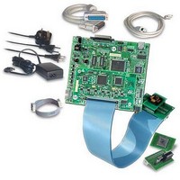
KIT EMULATOR FOR ST72321/324/521
Manufacturer
STMicroelectronics
Series
ST7-DVP3r
Type
Microcontrollerr
Datasheets
1.ST7MDT10-8DVP.pdf
(3 pages)
2.ST7MDT10-8DVP.pdf
(44 pages)
3.ST7MDT20-TEBDVP.pdf
(38 pages)
Specifications of ST7MDT20-DVP3
Contents
Main Emulation Board (MEB), Target Emulation Board (TEB), Cables, Power Supply and Documentation
For Use With/related Products
ST72321, ST72324, ST72521
Lead Free Status / RoHS Status
Lead free / RoHS Compliant
Other names
497-4874


ST7MDT20-DVP3 Probe User Guide
Caution:
Pin specification for J2 connector:
Pins #4, 18, 34 and 48 are reserved. They must not be connected.
1
3
5
7
9
11
13
15
17
19
21
23
25
27
29
31
33
35
37
39
41
43
45
47
49
Pin N°
GND
PA0
PA1
PA2
PA3
PA4
PA5
PA6
PA7
/RESET MCU reset
PB0
PB1
PB2
PB3
PB4
PB5
PB6
PB7
OSC1
PC0
PC1
PC2
PC3
PC4
PC5
Name
Table 6: Pin correspondence for W1 connector
to connect to GND
I/O port A bit 0
I/O port A bit 1
I/O port A bit 2
I/O port A bit 3
I/O port A bit 4
I/O port A bit 5
I/O port A bit 6
I/O port A bit 7
I/O port B bit 0
I/O port B bit 1
I/O port B bit 2
I/O port B bit 3
I/O port B bit 4
I/O port B bit 5
I/O port B bit 6
I/O port B bit 7
also called “OSCIN”
I/O port C bit 0
I/O port C bit 1
I/O port C bit 2
I/O port C bit 3
I/O port C bit 4
I/O port C bit 5
Description/
Comments
3 - Connecting to your application board
2
4
6
8
10
12
14
16
18
20
22
24
26
28
30
32
34
36
38
40
42
44
46
48
50
Pin N°
GND
reserved
GND
reserved
GND
reserved
GND
reserved
GND
Name
to connect to GND
to connect to GND
to connect to GND
to connect to GND
to connect to GND
Description/
Comments
27/38
Related parts for ST7MDT20-DVP3
Image
Part Number
Description
Manufacturer
Datasheet
Request
R

Part Number:
Description:
KIT CONNECTION ST7MDT20-DVP3
Manufacturer:
STMicroelectronics
Datasheet:
Part Number:
Description:
KIT CONNECTOR FOR STMDT20 44TQFP
Manufacturer:
STMicroelectronics
Datasheet:
Part Number:
Description:
BOARD TARGET EMULATION ST7-DVP
Manufacturer:
STMicroelectronics
Datasheet:
Part Number:
Description:
KIT CONNECTOR FOR STMDT20 80TQFP
Manufacturer:
STMicroelectronics
Datasheet:
Part Number:
Description:
KIT CONNECTOR FOR STMDT20 32TQFP
Manufacturer:
STMicroelectronics
Datasheet:
Part Number:
Description:
KIT CONNECTOR FOR STMDT20 64TQFP
Manufacturer:
STMicroelectronics
Datasheet:
Part Number:
Description:
BOARD EVALUATION/TRAINING/PROGRM
Manufacturer:
STMicroelectronics
Datasheet:
Part Number:
Description:
BOARD EVALUATION/TRAINING/PROGRM
Manufacturer:
STMicroelectronics
Datasheet:
Part Number:
Description:
BOARD PROGRAMMING SGL POS ST7
Manufacturer:
STMicroelectronics
Datasheet:
Part Number:
Description:
KIT DEVELOPMENT ST7
Manufacturer:
STMicroelectronics
Datasheet:

Part Number:
Description:
Low Cost, Real Time Emulator Series for ST7
Manufacturer:
STMICROELECTRONICS [STMicroelectronics]
Datasheet:
Part Number:
Description:
Full-featured, real time emulator series for ST7
Manufacturer:
STMICROELECTRONICS [STMicroelectronics]
Datasheet:
Part Number:
Description:
Programming board
Manufacturer:
STMICROELECTRONICS [STMicroelectronics]
Datasheet:
Part Number:
Description:
8-bit microcontroller with single voltage Flash memory, data EEPROM, ADC, timers, SPI
Manufacturer:
STMICROELECTRONICS [STMicroelectronics]
Datasheet:
Part Number:
Description:
In-Circuit Programmer
Manufacturer:
STMicroelectronics
Datasheet: