AT18F-DK3 Atmel, AT18F-DK3 Datasheet - Page 11
AT18F-DK3
Manufacturer Part Number
AT18F-DK3
Description
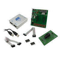
KIT CONFIG PROGRAM FOR AT18F FAM
Manufacturer
Atmel
Series
AT18Fr
Type
In-Circuit Emulator Systemr
Datasheet
1.ATF15XXDK3-SAX20.pdf
(22 pages)
Specifications of AT18F-DK3
Contents
2 Boards, Cable, CD, Samples
Processor To Be Evaluated
AT18F
Processor Series
AT18F
Interface Type
ISP, JTAG
Operating Supply Voltage
3.3 V
For Use With/related Products
AT18F Series
Lead Free Status / RoHS Status
Lead free / RoHS Compliant
Other names
Q4623814


3685A–CNFG–04/08
Hardware Description
2.1.7
2.1.8
2.1.9
2.1.10
2.1.11
2-6
ICCIO and ICCINT Jumpers
Voltage Regulators
Power Supply Switch and Power LED
Power Supply Jack and Power Supply Header
JTAG ISP Connector and TDO Selection Jumper
The ICCIO and ICCINT jumpers can be removed and used as ICC measurement points. When the jump-
ers are removed, current meters can be connected to the posts to measure the current consumption of
the target AT18F Series Configurators. When users are not using these jumpers to measure the current,
these jumpers must be set in order for the board and Configurator to operate.
Two voltage regulators, labeled VR1 and VR2, are used to independently generate and regulate the
VCCINT and VCCIO voltages from the 9V DC power supply. For details, please review the schematic of
the ATF15xx-DK3 Base Board of the AT18F-DK3 kit.
The Power Supply Switch, labeled POWER SWITCH, can be switched to the ON or OFF position, which
is used to turn on or off the power of the ATF15xx-DK3 Base Board of the AT18F-DK3 kit. It allows the
9V DC voltage at the Power Supply Jack to pass to the voltage regulators when it is in the ON position.
When the Power Supply Switch is turned ON, the Power LED (labeled POWER LED) will light up to indi-
cate that the ATF15xx-DK3 Base Board of the AT18F-DK3 kit is supplied with power.
The Atmel ATF15xx-DK3 Base Board of the AT18F-DK3 kit contains two different types of power supply
connectors labeled JPower and JP Power. Either one of these power supply connectors can be used to
connect a 9V DC power source to the board. The first power connector, labeled JPower, is a barrel
power jack with a 2.1 mm diameter post and it mates to a 2.1 mm (inner diameter) x 5.5 mm (outer diam-
eter) female plug. The second is the power supply header, labeled JP Power, is a 4-pin male
0.1-inch header with 0.025-inch square posts. The availability of these two types of power connectors
allows the users to choose the type of power supply equipment to use for ATF15xx-DK3 Base Board of
the AT18F-DK3 kit. However, please note that only one of these two power supply connectors should be
powered with a 9V DC source but not both at the same time.
The JTAG ISP Connector, labeled JTAG-IN, is used to connect the ATF15xx’s JTAG port pins (TCK,
TDI, TMS and TDO) through the ISP download cable to the parallel printer (LPT) port of a PC for JTAG
ISP programming of the AT18F Series Configurators. Polarized connectors are used on the ATF15xx-
DK3 Base Board of the AT18F-DK3 kit and ISP Download Cable (ATDH1151VPC) Rev 6.0 or later are
used to minimize connection problems. The PIN1 label at the bottom of the JTAG ISP connector indi-
cates the pin 1 position of the 10-pin header and further reduces the chance of connecting the ISP
Download Cable incorrectly.
To the left of the JTAG-IN connector, there are two columns of vias and they are labeled JTAG-OUT.
They are intended to allow the users to create a JTAG daisy chain to perform JTAG operations to multi-
ple AT18F Series Configurators. Users will need to solder the same type of connector as the one used
for JTAG-IN into the JTAG-OUT position in order to utilize this available feature.
AT18F-DK3 Configurator Development Kit User Guide
Related parts for AT18F-DK3
Image
Part Number
Description
Manufacturer
Datasheet
Request
R

Part Number:
Description:
ACCY USB CABLE JTAG ISP AT18F
Manufacturer:
Atmel
Datasheet:

Part Number:
Description:
DEV KIT FOR AVR/AVR32
Manufacturer:
Atmel
Datasheet:

Part Number:
Description:
INTERVAL AND WIPE/WASH WIPER CONTROL IC WITH DELAY
Manufacturer:
ATMEL Corporation
Datasheet:
Part Number:
Description:
Low-Voltage Voice-Switched IC for Hands-Free Operation
Manufacturer:
ATMEL Corporation
Datasheet:
Part Number:
Description:
MONOLITHIC INTEGRATED FEATUREPHONE CIRCUIT
Manufacturer:
ATMEL Corporation
Datasheet:
Part Number:
Description:
AM-FM Receiver IC U4255BM-M
Manufacturer:
ATMEL Corporation
Datasheet:
Part Number:
Description:
Monolithic Integrated Feature Phone Circuit
Manufacturer:
ATMEL Corporation
Datasheet:
Part Number:
Description:
Multistandard Video-IF and Quasi Parallel Sound Processing
Manufacturer:
ATMEL Corporation
Datasheet:
Part Number:
Description:
High-performance EE PLD
Manufacturer:
ATMEL Corporation
Datasheet:
Part Number:
Description:
8-bit Flash Microcontroller
Manufacturer:
ATMEL Corporation
Datasheet:
Part Number:
Description:
2-Wire Serial EEPROM
Manufacturer:
ATMEL Corporation
Datasheet: