CY8CKIT-001 Cypress Semiconductor Corp, CY8CKIT-001 Datasheet - Page 47
CY8CKIT-001
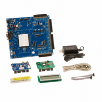
Manufacturer Part Number
CY8CKIT-001
Description
KIT DEV FOR PSOC3/5
Manufacturer
Cypress Semiconductor Corp
Series
PSoC® CapSenser
Type
MCUr
Datasheets
1.CY8CKIT-001.pdf
(2 pages)
2.CY8CKIT-001.pdf
(5 pages)
3.CY8CKIT-001.pdf
(116 pages)
4.CY8CKIT-001.pdf
(12 pages)
Specifications of CY8CKIT-001
Contents
Board, CD, CY8C29 & CY8C38 Modules, MiniProg3 Programmer/Debugger, Power Supply
Processor To Be Evaluated
CY8C29, CY8C38
Interface Type
RS-232, USB, JTAG
Operating Supply Voltage
3.3 V, 5 V
Lead Free Status / RoHS Status
Lead free / RoHS Compliant
For Use With/related Products
PSoC 1, PSoC 3 and PSoC 5
Lead Free Status / Rohs Status
Lead free / RoHS Compliant
Other names
428-2961
Available stocks
Company
Part Number
Manufacturer
Quantity
Price
Company:

Part Number:
CY8CKIT-001A
Manufacturer:
Cypress Semiconductor
Quantity:
135


3.1.3.2
CY8CKIT-001 PSoC Development Kit Guide, Doc. # 001-48651 Rev. **
main.c
/*******************************************************************************
* File Name: main.c
*
* Description:
*
*
*
*
*
/******************************************************************************
*
*
*
*
*
*
*
*******************************************************************************/
/******************************************************************************
*
*
*
*
*******************************************************************************/
/******************************************************************************
*
*
*
*
*
*
*
*
*
*
*
*
*
*
*
*******************************************************************************/
/******************************************************************************
*
*
*
*
*
*
*
*
*
*
*
*
*
This file provides source code for the ADC to LCD with DAC and UART example
project. The firmware takes a voltage output from a potentiometer and
displays the ADC raw count on an LCD. The raw count is also transmitted
serially. The raw count also determines the clock divider value of the clock
driving the DAC update rate.
PGA_1 Settings:(The PGA buffers the potentiometer voltage on P0.1 into the ADC)
LCD_1 Settings:
DelSig_1 Settings:
The ADC can read full range values from 0-5V, if the Ref Mux setting is
selected as (Vdd/2)+/- (Vdd/2) and Vdd = 5V. The ADC is configured for a
resolution of 8 bits, this is achieved by selecting the appropriate
configuration when placing the UM.
Counter8_1 Settings:
The Counter8_1 controls the update rate of the DAC. The DAC is updated
during ever TerminalCount ISR. The frequency of the TerminalCount ISR is
determined by the Counter Input Clock divided by the (Period value +1).
The Period Value of the counter is changed by the ADC reading. Thus the
frequency of the TerminalCount ISR can range from 125kHz (Period Value=1)
to 977Hz (Period Value = 255)
Gain
Input
Reference = AGND
AnalogBus = Disable
LCDPort
BarGraph = Disable
DataFormat
DataClock
ClockPhase
PosInput
NegInput
NegInputGain = Disconnected
PWM Output
PulseWidth
Clock
ClockSync
Enable
CompareOut
TerminalCountOut = None
= Port_2
= 1
= AnalogColumn_InputMUX_0
= Unsigned
= VC2 //VC2 = 24MHz/16/16 = 250kHz
= Normal
= ACB00 (PGA_1)
= ACB00
= None
= N/A
= VC2 // VC2 = 24MHz/16/16 = 250kHz
= Sync to SysClk
= High
= None
*Note this parameter is not used
*Note this parameter is not used
(P0.1)
Sample Projects
43
[+] Feedback
Related parts for CY8CKIT-001
Image
Part Number
Description
Manufacturer
Datasheet
Request
R

Part Number:
Description:
KIT DEV FOR PSOC3/5
Manufacturer:
Cypress Semiconductor Corp
Datasheet:

Part Number:
Description:
PSoC1/3/5 Development Kit
Manufacturer:
Cypress Semiconductor Corp
Datasheet:

Part Number:
Description:
KIT DEV PSOC PROC MODULE CY8C38
Manufacturer:
Cypress Semiconductor Corp

Part Number:
Description:
KIT DEV PSOC PROC MODULE CY8C29
Manufacturer:
Cypress Semiconductor Corp

Part Number:
Description:
KIT DEV PSOC ANALOG VOLTMETER
Manufacturer:
Cypress Semiconductor Corp
Datasheet:

Part Number:
Description:
KIT DEV PSOC5 FIRST TOUCH
Manufacturer:
Cypress Semiconductor Corp
Datasheet:

Part Number:
Description:
KIT DEV PSOC3 FIRSTTOUCH STARTER
Manufacturer:
Cypress Semiconductor Corp
Datasheet:
Part Number:
Description:
KIT DEV PROC MODULE PSOC5
Manufacturer:
Cypress Semiconductor Corp
Datasheet:

Part Number:
Description:
KIT PSOC CY8C28 FAMILY PROCESSOR
Manufacturer:
Cypress Semiconductor Corp
Datasheet:

Part Number:
Description:
KIT PSOC MINIPROG3 PROGRAM DEBUG
Manufacturer:
Cypress Semiconductor Corp
Datasheet:

Part Number:
Description:
KIT EVAL POWERLINE HIGH VOLT
Manufacturer:
Cypress Semiconductor Corp
Datasheet:

Part Number:
Description:
KIT PSOC FIRST TOUCH
Manufacturer:
Cypress Semiconductor Corp
Datasheet:

Part Number:
Description:
EVAL KIT WORLDTOUR2
Manufacturer:
Cypress Semiconductor Corp
Datasheet:

Part Number:
Description:
KIT UNIVERSAL CAPSENSE CTRLR
Manufacturer:
Cypress Semiconductor Corp
Datasheet:
