XCARD XC-3 XMOS, XCARD XC-3 Datasheet - Page 7
XCARD XC-3
Manufacturer Part Number
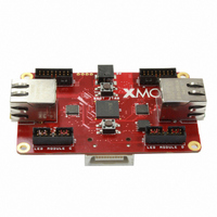
XCARD XC-3
Description
BOARD KIT XS1-G4 LED CTRL TILE
Manufacturer
XMOS
Series
XCore™r
Type
MCUr
Specifications of XCARD XC-3
Design Resources
XC-3 Schematic
Contents
2 Boards, Cable, Power Supply
For Use With/related Products
XS1-G4
Lead Free Status / RoHS Status
Lead free / RoHS Compliant
Other names
880-1015


XC-3 Hardware Manual (1.3)
6 I/O Expansion Header [F]
The I/O pins of processor 0 are brought out to a general purpose I/O expansion
area on one side of the card. The area has 0.1” pitch through-plated holes and is
suitable for use with IDC headers. To provide maximum flexibility, no headers are
fitted, allowing the most suitable type to be selected depending on the design. The
routing of the I/O and power pins in the expansion header is shown below:
The expansion header provides a bank of nine I/O pins, which are mapped to the
ports as described in the table below:
The pins from the bank can be configured as either two 4-bit ports or a single 8-bit
port.
Pin
X0D26
X0D27
X0D28
X0D29
X0D30
X0D31
X0D32
X0D33
X0D38 P1O0
1b
www.xmos.com
4b
P4E0 P8C0
P4E1 P8C1
P4F0 P8C2
P4F1 P8C3
P4F2 P8C4
P4F3 P8C5
P4E2 P8C6
P4E3 P8C7
Port
8b
X0D38
X0D26
X0D28
X0D30
X0D32
3V3
PORT_GPIO_CLK
NC
5V
Processor
1
15
GPIO
0
16
2
NC
X0D27
X0D29
GND
X0D31
X0D33
NC
GND
7/14
Related parts for XCARD XC-3
Image
Part Number
Description
Manufacturer
Datasheet
Request
R

Part Number:
Description:
BOARD DEV KIT XS1-G4 ETHERNET
Manufacturer:
XMOS
Datasheet:

Part Number:
Description:
BOARD DEV KIT XS1-G4
Manufacturer:
XMOS
Datasheet:

Part Number:
Description:
DEV KIT EVENT-DRIVEN PROC XS1-L1
Manufacturer:
XMOS
Datasheet:

Part Number:
Description:
ADAPTER USB DEBUGGER JTAG XSYS2
Manufacturer:
XMOS
Datasheet:

Part Number:
Description:
BOARD DEV KIT XS1-G4
Manufacturer:
XMOS
Datasheet:

Part Number:
Description:
IC MPU 32BIT SINGLE CORE 64LQFP
Manufacturer:
XMOS
Datasheet:

Part Number:
Description:
IC MPU 32BIT SINGLE CORE 64LQFP
Manufacturer:
XMOS
Datasheet:
Part Number:
Description:
IC MPU 32BIT SINGLE CORE 64LQFP
Manufacturer:
XMOS
Datasheet:

Part Number:
Description:
IC MPU 32BIT SINGLE CORE 64LQFP
Manufacturer:
XMOS
Datasheet:
Part Number:
Description:
IC MPU 32BIT SINGLE CORE 64LQFP
Manufacturer:
XMOS
Datasheet:

Part Number:
Description:
IC MPU 32BIT SINGLE CORE 128TQFP
Manufacturer:
XMOS
Datasheet:
Part Number:
Description:
IC MPU 32BIT SINGLE CORE 64LQFP
Manufacturer:
XMOS
Datasheet:
Part Number:
Description:
IC MPU 32BIT SINGLE CORE 128TQFP
Manufacturer:
XMOS
Datasheet:
Part Number:
Description:
IC MPU 32BIT SINGLE CORE 128TQFP
Manufacturer:
XMOS
Datasheet:

Part Number:
Description:
IC MPU 32BIT DUAL CORE 124QFN
Manufacturer:
XMOS
Datasheet: