XCARD XC-3 XMOS, XCARD XC-3 Datasheet
XCARD XC-3
Specifications of XCARD XC-3


Related parts for XCARD XC-3


XCARD XC-3 Summary of contents
Page 1
... XC-3 Hardware Manual Publication Date: 2009/09/25 Copyright © 2009 XMOS Ltd. All Rights Reserved. Version 1.3 ...
Page 2
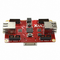
... PC. The card is fitted with four plastic feet, which can be removed to provide access to mounting holes for product integration. The following sections in this document provide a detailed description of these components SPI Flash Memory I Power Connector J XSYS Connector K Power Regulator L 20MHz Crystal Oscillator (XCore™) M 25MHz Crystal Oscillator (Transceiver) www.xmos.com 2/ ...
Page 3
... The processors have ports that are directly connected to the I/O pins. 3 LED Module In [B] The I/O pins of processor 0 have been brought out to a LED Module Input connector that can be used to connect to a 16-way 2mm IDC connector CLK GND G1 GND NC GND NC GND 15 16 www.xmos.com 3/14 ...
Page 4
... The connector provides a bank of 12 I/O pins, which are mapped to the ports as described in the table on the next page: Port Processor PORT_LED_IN_CLK P8B0 PORT_LED_IN [R0] P8B1 PORT_LED_IN [G0] P8B2 PORT_LED_IN [B0] P8B3 PORT_LED_IN [R1] P8B4 PORT_LED_IN [G1] P8B5 PORT_LED_IN [B1 GND G1 GND ADR1 GND LTCH GND 15 16 www.xmos.com 4/14 ...
Page 5
... MAC level protocols are implemented in software. Ethernet_0 The I/O pins on the ethernet PHY are mapped to the ports as described in the table on the following page: Port Processor P4A0 PORT_LED_OUT_ADDR [0] P4A1 PORT_LED_OUT_ADDR [1] P4A2 PORT_LED_OUT_ADDR [2] PORT_LED_OUT_R0 PORT_LED_OUT_G0 PORT_LED_OUT_B0 PORT_LED_OUT_R1 PORT_LED_OUT_G1 PORT_LED_OUT_B1 PORT_LED_OUT_CLK PORT_LED_OUT_LATCH LED_OUT_OE www.xmos.com 5/14 Ethernet_1 ...
Page 6
... PORT_ETH_TXCLK_0 PORT_ETH_RXDV_0 PORT_ETH_TXEN_0 P4C0 PORT_ETH_RXD_0 [0:1] P4C1 P4D0 P4D1 PORT_ETH_TXD_0 P4D2 P4D3 P4C2 PORT_ETH_RXD_0 [2:3] P4C3 PORT_ETH_MDIO_0 PORT_ETH_RST_N PORT_ETH_MDC_0 PORT_ETH_RXCLK_1 P4E0 PORT_ETH_RXD_1 [0:1] P4E1 P4F0 P4F1 PORT_ETH_TXD_1 P4F2 P4F3 P4E2 PORT_ETH_RXD_1 [2:3] P4E3 PORT_ETH_RXDV_1 PORT_ETH_RXER_1 PORT_ETH_TXCLK_1 PORT_ETH_TXEN_1 PORT_ETH_MDC_1 PORT_ETH_MDIO_1 www.xmos.com 6/14 ...
Page 7
... The pins from the bank can be configured as either two 4-bit ports or a single 8-bit port. 1 X0D38 X0D26 X0D28 3V3 X0D30 X0D32 Port Processor P4E0 P8C0 P4E1 P8C1 P4F0 P8C2 P4F1 P8C3 P4F2 P8C4 P4F3 P8C5 P4E2 P8C6 P4E3 P8C7 PORT_GPIO_CLK www.xmos.com 7/ X0D27 X0D29 GND X0D31 X0D33 NC GND 16 0 GPIO ...
Page 8
... XS1-G4’s processors. The XSYS connector is tied to global system I/O pins that provide JTAG control, system reset, processor debug, bidirectional UART and one XMOS Link. The routing of these I/O pins along with the power pins is shown on the following page: www ...
Page 9
... XC-3 Hardware Manual (1.3) The XMOS XTAG connector converts between XSYS and USB 2.0, allowing the XC connected to most PCs. On power on, the XS1-G4 boots from the on-board flash memory. The XS1-G4 can then be put into JTAG mode by the PC, which then boots another program. ...
Page 10
... XC-3 Hardware Manual (1.3) The XMOS Development Tools include the XFLASH utility for programming compiled programs into the flash memory. XC-3 designs may also access the flash memory at run-time by interfacing with the above ports. 11 Crystal Oscillator [L and M] The XS1-G4 is clocked at 20MHz by a crystal oscillator on the card. Each processor is clocked at 400MHz, the I/O ports at 100MHz on-chip phase-locked loop (PLL) ...
Page 11
... The table on the following page provides a full description of the port-to-pin mappings described throughout this document: Processor 2 ETHERNET TRANSCEIVER ETHERNET_0 System Services XS1-G4 PGOOD RESET RESET CLOCK 25MHz XTO www.xmos.com 11/14 ETHERNET TRANSCEIVER ETHERNET_1 LINK UART RX UART TX TDI TDO TMS TCK TRST DEBUG ...
Page 12
... PORT_LED_IN_R1 P16A12 PORT_LED_IN_G1 P16A13 PORT_LED_IN_B1 P16A14 P16A15 PORT_LED_OUT_G0 PORT_LED_OUT_B0 PORT_LED_OUT_R1 PORT_LED_OUT_G1 GPIO PORT_LED_OUT_B1 PORT_LED_OUT_CLK PORT_LED_OUT_LATCH PORT_LED_OUT_OE PORT_GPIO_CLK PORT_UART_RX www.xmos.com 12/14 2 PORT_ETH_RXCLK_0 PORT_ETH_RXER_0 PORT_ETH_TXCLK_0 PORT_ETH_RXDV_0 PORT_ETH_TXEN_0 PORT_ETH_RXD_0 [0:1] PORT_ETH_TXD_0 PORT_ETH_RXD_0 [2:3] PORT_ETH_MDIO_0 PORT_ETH_RST_N PORT_ETH_MDC_0 PORT_ETH_RXCLK_1 PORT_ETH_RXD_1 [0:1] PORT_ETH_TXD_1 [0:3] PORT_ETH_RXD_1 [2:3] PORT_ETH_RXDV_1 ...
Page 13
... PORT_LED_IN XS1_PORT_1A PORT_ETH_RXCLK_0 XS1_PORT_1B PORT_ETH_RXER_0 XS1_PORT_1C PORT_ETH_TXCLK_0 XS1_PORT_1D PORT_ETH_RXDV_0 XS1_PORT_1E PORT_ETH_TXEN_0 XS1_PORT_1G PORT_ETH_MDIO_0 XS1_PORT_1G PORT_ETH_RST_N XS1_PORT_1I PORT_ETH_MDC_0 XS1_PORT_1J PORT_ETH_RXCLK_1 2 XS1_PORT_1K PORT_ETH_RXDV_1 XS1_PORT_1L PORT_ETH_RXER_1 XS1_PORT_1M PORT_ETH_TXCLK_1 XS1_PORT_1N PORT_ETH_TXEN_1 XS1_PORT_1O PORT_ETH_MDC_1 XS1_PORT_1P PORT_ETH_MDIO_1 XS1_PORT_4C PORT_ETH_RXD_0 XS1_PORT_4D PORT_ETH_TXD_0 XS1_PORT_4E PORT_ETH_RXD_1 XS1_PORT_4F PORT_ETH_TXD_1 www.xmos.com 13/14 ...
Page 14
... XMOS Ltd. is the owner or licensee of this design, code, or Information (collectively, the “Information”) and is providing it to you “AS IS” with no warranty of any kind, express or implied and shall have no liability in relation to its use. XMOS Ltd. makes no representation that the Information, or any particular implementation thereof will be free from any claims of infringement and again, shall have no liability in relation to any such claims ...