DK-SI-4SGX230N Altera, DK-SI-4SGX230N Datasheet - Page 16
DK-SI-4SGX230N
Manufacturer Part Number
DK-SI-4SGX230N
Description
KIT DEV STRATIX IV 4SGX230N/C2
Manufacturer
Altera
Series
Stratix® IV GXr
Type
FPGAr
Datasheet
1.DK-SI-4SGX230N.pdf
(30 pages)
Specifications of DK-SI-4SGX230N
Contents
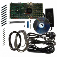
Board, Cables, CD, Power Supply
Silicon Manufacturer
Altera
Core Architecture
FPGA
Core Sub-architecture
Stratix
Silicon Core Number
EP4S
Silicon Family Name
Stratix IV GX
Rohs Compliant
Yes
For Use With/related Products
EP4SGX230
Lead Free Status / RoHS Status
Lead free / RoHS Compliant
Other names
544-2592
DK-SI-4SGX230N/C2
DK-SI-4SGX230N/C2
Available stocks
Company
Part Number
Manufacturer
Quantity
Price


6–2
LCD Information
Running the Demonstration Application and Test Designs
Transceiver Signal Integrity Development Kit, Stratix IV GX Edition User Guide
1
1
1
c
4. Click Start to download the selected file to the FPGA. The FPGA is configured
To determine if the appropriate test design .sof is programmed, check the LCD for the
test design number. Refer to
The LCD shows the following information:
■
■
■
The power values shown for the VCCA_L/R and the VCCH_GXB assume that the
jumper settings are set to 3.0 V and 2.5 V, respectively. Click the Help button to see the
required jumper settings.
The demonstration application communicates with the set of test designs provided
with the kit. You can change the various transceiver parameters that are described in
this section.
To run the application, make sure that the board is powered up properly and there is a
USB cable attached, then go to the <install
dir>\kits\stratixIVGX_4sgx230_si\demos\ directory and double-click on
stratixIVGX_si_demo.exe file. Ensure that the Stratix IV FPGA is programmed with
the .sof specified in
To enable the application to communicate with the board, click the Connect button. To
close the application, click the Disconnect button
Because the demonstration application communicates with the board using the same
interface as the Quartus II Programmer or SignalTap
you can run only one of these applications at a time.
The application will not run unless the USB cable is attached, power is applied, and
the correct .sof is programmed to the Stratix IV GX FPGA as specified in
page
For operating system stability, keep the USB cable connected and the board
powered ON when running the demonstration application.
when the progress bar reaches 100%.
The Stratix IV GX device junction temperature in Celsius.
The power in watts for the different transceivers (VCCA_L/R, VCCT, VCCR,
VCCH_GXB, VCCL_GXB) and core (VCC) voltage supply rails. Turn the rotary
switch SW16 to observe the different voltage supply values.
To learn more about the switch position for displaying the various supply rail
values on the LCD, click the Help button in the demonstration application.
The sof/pof number that is programmed is indicated by ‘pof’ followed by the
number.
6–1.
Table 6–1 on page
“LCD Information”
Chapter 6: Stratix IV GX Transceiver Signal Integrity Demonstration
6–1.
for more information.
(Figure
®
II Embedded Logic Analyzer,
6–1).
© February 2009 Altera Corporation
Table 6–1 on
LCD Information
Related parts for DK-SI-4SGX230N
Image
Part Number
Description
Manufacturer
Datasheet
Request
R

Part Number:
Description:
SI KIT W/SII GX EP2SGX90N
Manufacturer:
Altera
Datasheet:

Part Number:
Description:
KIT DEV STRATIX IV TRANSCEIVER
Manufacturer:
Altera
Datasheet:

Part Number:
Description:
KIT DEV STRATIX V FPGA 5SGXEA7
Manufacturer:
Altera
Datasheet:

Part Number:
Description:
Programmable Logic IC Development Tools FPGA Starter Kit For Stratix V 5SGXEA7
Manufacturer:
Altera Corporation
Part Number:
Description:
Programmable Logic IC Development Tools FPGA Starter Kit For Stratix V 5SGTMC7
Manufacturer:
Altera Corporation
Part Number:
Description:
Programmable Logic IC Development Tools FPGA Starter Kit For Stratix V 5SGTMC7 ES
Manufacturer:
Altera Corporation

Part Number:
Description:
CYCLONE II STARTER KIT EP2C20N
Manufacturer:
Altera
Datasheet:
Part Number:
Description:
CPLD, EP610 Family, ECMOS Process, 300 Gates, 16 Macro Cells, 16 Reg., 16 User I/Os, 5V Supply, 35 Speed Grade, 24DIP
Manufacturer:
Altera Corporation
Datasheet:
Part Number:
Description:
CPLD, EP610 Family, ECMOS Process, 300 Gates, 16 Macro Cells, 16 Reg., 16 User I/Os, 5V Supply, 15 Speed Grade, 24DIP
Manufacturer:
Altera Corporation
Datasheet:
Part Number:
Description:
Manufacturer:
Altera Corporation
Datasheet:
Part Number:
Description:
CPLD, EP610 Family, ECMOS Process, 300 Gates, 16 Macro Cells, 16 Reg., 16 User I/Os, 5V Supply, 30 Speed Grade, 24DIP
Manufacturer:
Altera Corporation
Datasheet:
Part Number:
Description:
High-performance, low-power erasable programmable logic devices with 8 macrocells, 10ns
Manufacturer:
Altera Corporation
Datasheet:
Part Number:
Description:
High-performance, low-power erasable programmable logic devices with 8 macrocells, 7ns
Manufacturer:
Altera Corporation
Datasheet: