DEMO9S08SV16 Freescale Semiconductor, DEMO9S08SV16 Datasheet - Page 10
DEMO9S08SV16
Manufacturer Part Number
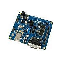
DEMO9S08SV16
Description
BOARD DEMO FOR SV16 FAMILY
Manufacturer
Freescale Semiconductor
Type
MCUr
Specifications of DEMO9S08SV16
Contents
Board
Processor To Be Evaluated
S08
Data Bus Width
8 Bit
Interface Type
USB, RS-232
Operating Supply Voltage
5 V
Silicon Manufacturer
Freescale
Core Architecture
HCS08
Core Sub-architecture
HCS08
Silicon Core Number
MC9S08
Silicon Family Name
S08SV
Kit Contents
Board, Quick Start Guide, User Guide
Rohs Compliant
Yes
For Use With/related Products
MC9S08SV
Lead Free Status / RoHS Status
Lead free / RoHS Compliant


D E M O 9 S 0 8 S V 1 6 / F L 1 6
J U N E
5 ,
2 0 0 9
U S E R
G U I D E
RESET SWITCH
The RESET switch applies an asynchronous RESET to the MCU. The RESET switch is
connected directly to the RESET* input on the MCU. Pressing the RESET switch applies a
low voltage level to the RESET* input. A pull-up bias resistor allows normal MCU operation.
Shunt capacitance ensures an adequate input pulse width.
Both the MC9S08SV16 and MC9S08FL16 MCU’s apply a multiplexed RESET* input. To use
the RESET switch, the RESET pin must be enabled (SOPT1_RSTPE).
Refer to the
MC9S08SV16 or MC9S08FL16 Reference Manual for details on configuring using the RESET*
input.
LOW VOLTAGE RESET
Both the MC9S08SV16 and the MC9S08FL16 apply an internal Low Voltage Detect (LVD)
circuitry. The LVD holds the MCU in reset until applied voltage reaches the appropriate level.
The LVD also protects against under-voltage conditions. Consult the MC9S08SV16 or
MC9S08FL16 Reference Manual for details on LVD operation.
TIMING
Default timing for the DEMO9S08SV16/FL16 is provided by the MC9S08SV16 or
MC9S08FL16 internal timing source which is active out of RESET. External circuitry for an
external 32 kHz XTAL oscillator is provided; however, these components are not populated in
default configuration.
Refer to the MC9S08SV16 or MC9S08FL16 Reference Manual for
details on configuring the timing source.
COMMUNICATIONS
Serial communication on the DEMO9S08SV16/FL16 board is supported through an RS-232
physical layer interface and DB-9 connector and through a virtual serial port implemented in
the USB-BDM. The COM_SEL option header selects between the applied serial function.
NOTE: Virtual serial port services are not functional as of the date of this document
COM Port
An RS-232 transceiver provides RS-232 to TTL/CMOS logic level translation between the
COM connector and the MCU. The COM connector is a 9-pin Dsub, right-angle connector. A
ferrite bead on shield ground provides conducted immunity protection. Communication signals
TXD and RXD are routed from the transceiver to the MCU. These signals are also available
on connector J1. Hardware flow control signals RTS and CTS are available on the logic side
10
Related parts for DEMO9S08SV16
Image
Part Number
Description
Manufacturer
Datasheet
Request
R

Part Number:
Description:
Manufacturer:
Freescale Semiconductor, Inc
Datasheet:
Part Number:
Description:
Manufacturer:
Freescale Semiconductor, Inc
Datasheet:
Part Number:
Description:
Manufacturer:
Freescale Semiconductor, Inc
Datasheet:
Part Number:
Description:
Manufacturer:
Freescale Semiconductor, Inc
Datasheet:
Part Number:
Description:
Manufacturer:
Freescale Semiconductor, Inc
Datasheet:
Part Number:
Description:
Manufacturer:
Freescale Semiconductor, Inc
Datasheet:
Part Number:
Description:
Manufacturer:
Freescale Semiconductor, Inc
Datasheet:
Part Number:
Description:
Manufacturer:
Freescale Semiconductor, Inc
Datasheet:
Part Number:
Description:
Manufacturer:
Freescale Semiconductor, Inc
Datasheet:
Part Number:
Description:
Manufacturer:
Freescale Semiconductor, Inc
Datasheet:
Part Number:
Description:
Manufacturer:
Freescale Semiconductor, Inc
Datasheet:
Part Number:
Description:
Manufacturer:
Freescale Semiconductor, Inc
Datasheet:
Part Number:
Description:
Manufacturer:
Freescale Semiconductor, Inc
Datasheet:
Part Number:
Description:
Manufacturer:
Freescale Semiconductor, Inc
Datasheet:
Part Number:
Description:
Manufacturer:
Freescale Semiconductor, Inc
Datasheet: