DEMO9S08SV16 Freescale Semiconductor, DEMO9S08SV16 Datasheet
DEMO9S08SV16
Specifications of DEMO9S08SV16


Related parts for DEMO9S08SV16

DEMO9S08SV16 Summary of contents
Page 1
... DEMO9S08SV16/FL16 Demonstration Board for Freescale MC9S08SV16 or MC9S08FL16 Microcontroller USER GUIDE Web Site: Support: www.axman.com support@axman.com ...
Page 2
CAUTIONARY NOTES .............................................................................................................. 4 TERMINOLOGY ......................................................................................................................... 4 FEATURES ................................................................................................................................ 5 REFERENCES ........................................................................................................................... 6 MEMORY MAP .......................................................................................................................... 6 SOFTWARE DEVELOPMENT ................................................................................................... 7 DEVELOPMENT SUPPORT ...................................................................................................... 7 INTEGRATED BDM .............................................................................................................. 7 BDM_PORT HEADER ...
Page 3
Figure 1: Memory Map................................................................................................................ 6 Figure 2: BDM_PORT Header .................................................................................................... 7 Figure 3: V_SEL ...
Page 4
... EMC Information on the DEMO9S08SV16/FL16 board: a) This product as shipped from the factory with associated power supplies and cables, has been verified to meet with requirements of CE and the FCC as a CLASS A product. ...
Page 5
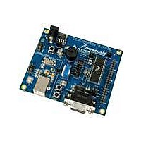
... FEATURES The DEMO9S08SV16/FL16 is a demonstration board for the MC9S08SV16 or MC9S08FL16 microcontroller. Application development is quick and easy with the integrated, Open-Source, USB-BDM, sample software tools, and examples. provided to allow use of a BDM_PORT cable. One, 40-pin connector provides access to all IO signals on the target MCU. ...
Page 6
... NOTE: The memory map above applies to the MC9S08SV16 and MC9S08FL16 microcontrollers DEMO9S08SV16/FL16 User Guide (this document) DEMO9S08SV16/FL16 Schematic Rev. A DEMO9S08SV16/FL16 Top Silk, Rev A DEMO9S08SV16/FL16 Default Shunt Placement DEMO9S08FL16 LED Demo Application DEMO9S08SV16 LED Demo Application Refer to the MC9S08SV16 or MC9S08FL16 Reference Manual ...
Page 7
... BDM_PORT header allows connecting an external HCS12/HCS08 BDM cable. The BDM_PORT header is not installed in default configurations. Integrated BDM The DEMO9S08SV16/FL16 board features an integrated Open Source BDM (OSBDM-JM60) based on the Freescale MC9S08JM60 MCU. The integrated USB BDM supports application development and debugging via background debug mode. ...
Page 8
... POWER The DEMO9S08SV16/FL16 may be powered from the integrated USB-BDM or from an on- board voltage regulator and external power connector. The desired power source is selected using the PWR_SEL option header. For application development and debug, the board may be powered from the integrated USB BDM ...
Page 9
not configure the target board to draw more than 300mA when powered from ...
Page 10
... Refer to the MC9S08SV16 or MC9S08FL16 Reference Manual for details on configuring the timing source. COMMUNICATIONS Serial communication on the DEMO9S08SV16/FL16 board is supported through an RS-232 physical layer interface and DB-9 connector and through a virtual serial port implemented in the USB-BDM. The COM_SEL option header selects between the applied serial function. ...
Page 11
the RS-232 transceiver and are routed to test point vias located near the transceiver. RTS has been biased properly to provide handshaking if required. RS-232 signals TXD and RXD are ...
Page 12
... GND 5 USER OPTIONS The DEMO9S08SV16/FL16 includes various input and output devices to aid application development and debug. User I/O includes 2 momentary pushbutton switches, 2 green LEDs, 1 potentiometer, 1 temperature sensor, and 1 piezo buzzer. Each device may be enabled or disabled individually with the USER_EN option header. Each user enable is clearly marked as to functionality ...
Page 13
Temperature Sensor A surface-mount, NTC Thermistor (B = 3900) is installed at location RZ1. ...
Page 14
MCU I/O PORT The MCU I/O PORT connector provides access to the MC9S08SV16 or MC9S08FL16 I/O signals. Figure 7 below show the pin-out for the MCU I/O connector. Figure 7: MCU ...