TOOLSTICK540DC Silicon Laboratories Inc, TOOLSTICK540DC Datasheet - Page 249
TOOLSTICK540DC
Manufacturer Part Number
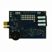
TOOLSTICK540DC
Description
DAUGHTER CARD TOOLSTICK F540
Manufacturer
Silicon Laboratories Inc
Series
ToolStickr
Type
MCUr
Datasheets
1.TOOLSTICK540DC.pdf
(274 pages)
2.TOOLSTICK540DC.pdf
(16 pages)
3.TOOLSTICK540DC.pdf
(12 pages)
Specifications of TOOLSTICK540DC
Contents
Daughter Card
Processor To Be Evaluated
C8051F54x
Processor Series
C8051F54x
Interface Type
USB
Operating Supply Voltage
2.7 V to 3.6 V
Lead Free Status / RoHS Status
Lead free / RoHS Compliant
For Use With/related Products
C8051F54x
For Use With
336-1345 - TOOLSTICK BASE ADAPTER336-1182 - ADAPTER USB DEBUG FOR C8051FXXX
Lead Free Status / Rohs Status
Lead free / RoHS Compliant
Other names
336-1717


24. Programmable Counter Array
The Programmable Counter Array (PCA0) provides enhanced timer functionality while requiring less CPU
intervention than the standard 8051 counter/timers. The PCA consists of a dedicated 16-bit counter/timer
and six 16-bit capture/compare modules. Each capture/compare module has its own associated I/O line
(CEXn) which is routed through the Crossbar to Port I/O when enabled. The counter/timer is driven by a
programmable timebase that can select between six sources: system clock, system clock divided by four,
system clock divided by twelve, the external oscillator clock source divided by 8, Timer 0 overflows, or an
external clock signal on the ECI input pin. Each capture/compare module may be configured to operate
independently in one of six modes: Edge-Triggered Capture, Software Timer, High-Speed Output, Fre-
quency Output, 8 to 11-Bit PWM, or 16-Bit PWM (each mode is described in Section
“24.3. Capture/Compare Modules” on page 252). The external oscillator clock option is ideal for real-time
clock (RTC) functionality, allowing the PCA to be clocked by a precision external oscillator while the inter-
nal oscillator drives the system clock. The PCA is configured and controlled through the system controller's
Special Function Registers. The PCA block diagram is shown in Figure 24.1
Important Note: The PCA Module 5 may be used as a watchdog timer (WDT), and is enabled in this mode
following a system reset. Access to certain PCA registers is restricted while WDT mode is enabled .
See Section 24.4 for details.
Capture/Compare
Module 0
SYSCLK/12
SYSCLK/4
Timer 0 Overflow
ECI
SYSCLK
External Clock/8
Capture/Compare
Module 1
CLOCK
MUX
PCA
Figure 24.1. PCA Block Diagram
16-Bit Counter/Timer
Capture/Compare
Module 2
Crossbar
Rev. 1.1
Port I/O
Capture/Compare
Module 3
Capture/Compare
Module 4
C8051F54x
Capture/Compare
Module 5 / WDT
249
Related parts for TOOLSTICK540DC
Image
Part Number
Description
Manufacturer
Datasheet
Request
R

Part Number:
Description:
KIT TOOL EVAL SYS IN A USB STICK
Manufacturer:
Silicon Laboratories Inc
Datasheet:

Part Number:
Description:
TOOLSTICK DEBUG ADAPTER
Manufacturer:
Silicon Laboratories Inc
Datasheet:

Part Number:
Description:
TOOLSTICK BASE ADAPTER
Manufacturer:
Silicon Laboratories Inc
Datasheet:

Part Number:
Description:
TOOLSTICK DAUGHTER CARD
Manufacturer:
Silicon Laboratories Inc
Datasheet:

Part Number:
Description:
TOOLSTICK DAUGHTER CARD
Manufacturer:
Silicon Laboratories Inc
Datasheet:

Part Number:
Description:
TOOLSTICK DAUGHTER CARD
Manufacturer:
Silicon Laboratories Inc
Datasheet:

Part Number:
Description:
TOOLSTICK PROGRAMMING ADAPTER
Manufacturer:
Silicon Laboratories Inc
Datasheet:

Part Number:
Description:
TOOLSTICK DAUGHTER CARD
Manufacturer:
Silicon Laboratories Inc
Datasheet:

Part Number:
Description:
KIT STARTER TOOLSTICK
Manufacturer:
Silicon Laboratories Inc
Datasheet:

Part Number:
Description:
KIT UNIVERSITY TOOLSTICK STARTER
Manufacturer:
Silicon Laboratories Inc
Datasheet:

Part Number:
Description:
DAUGHTER CARD TOOLSTICK F330
Manufacturer:
Silicon Laboratories Inc
Datasheet:

Part Number:
Description:
CARD DAUGHTER UNIVRSTY TOOLSTICK
Manufacturer:
Silicon Laboratories Inc
Datasheet:

Part Number:
Description:
DAUGHTER CARD TOOLSTICK F582
Manufacturer:
Silicon Laboratories Inc
Datasheet:

Part Number:
Description:
DAUGHTER CARD TOOLSTICK F500
Manufacturer:
Silicon Laboratories Inc
Datasheet:

Part Number:
Description:
DAUGHTER CARD TOOLSTICK F560
Manufacturer:
Silicon Laboratories Inc
Datasheet: