SDK-XAM3517-10-256512R Logic, SDK-XAM3517-10-256512R Datasheet - Page 9
SDK-XAM3517-10-256512R
Manufacturer Part Number
SDK-XAM3517-10-256512R
Description
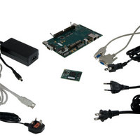
KIT DEV ZOOM EXPERIMENTER AM3517
Manufacturer
Logic
Series
Zoom™r
Type
Single Board Computers (SBC)r
Specifications of SDK-XAM3517-10-256512R
Contents
Board, Adapter, Cables, Documentation, Power Supply, Software
For Use With/related Products
AM3517
Lead Free Status / RoHS Status
Lead free / RoHS Compliant
Other names
460-3486
SDK-XAM3517-10-256512R
SDK-XAM3517-10-256512R


4.2
4.3
4.4
4.5
5
PN 1014539 Rev 1
Connect the Application Board
1. Make sure your AM3517 EVM Development Kit is powered off.
2. Align the application board over the three BTB expansion connectors on the eXperimenter
3. Press straight down on the application board, applying even pressure over the three
4. Visually verify that the BTB expansion connectors on the Application board and baseboard
5. Four screws and nuts are included with the kit to secure the application board to the
6. To disconnect the application board: remove the screws holding the boards together and then
Application Board Feature Usage
Some of the components on the EVM kit run off the same bus, so not every feature can be used
at the same time. The following features are mutually exclusive of each other since they share
MMC2:
The wireless daughterboard interface can be enabled or disabled by switch S11:4 on the
application board. The other features are controlled through software. This is something to take
into consideration if intending to use the application board with custom software for the SOM.
In addition, the application board supports composite, component, and S-Video analog video
inputs, as well as a camera digital input. All input devices may be connected simultaneously, but
only one video input device may be selected at a time. The selection between any analog input
and the camera input is made with switches S11:1 and S11:2 on the application board. The
choice of analog input is controlled through software.
Application Board Ethernet Jacks
The Ethernet jacks located on the application board are connected to the SMSC LAN9311
Ethernet chip on the application board. This chip connects to the processor GPMC bus and is
independent of the Ethernet jack located on the baseboard.
User Interface Buttons
Ten user interface buttons are available on the application board to interact with software. All of
the buttons run through an I/O switch controlled by I2C. Five of the interface buttons are also
connected in parallel with a five-way navigation knob.
Connect the Wi-Fi Antenna to the SOM-M2
NOTE: This section only applies to the Zoom AM3517 EVM Development Kit.
The antenna included with the AM3517 EVM Development Kit provides reception for 802.11b/g
Ethernet or Bluetooth signals. Only connect the antenna if 802.11 Ethernet or Bluetooth is
required for your demo or development efforts.
baseboard. Please refer to the diagram in Section 3.1 for the location of the connectors.
baseboard BTB expansion connectors.
have mated correctly.
baseboard; a Phillips #1 screwdriver is required (not included). Secure the screws through
the board holes with the nuts on the bottom side of the boards. IMPORTANT NOTE: Only
finger tighten the screws. Over-tightening the screws may permanently damage the boards.
pull up on the board above the BTB expansion connectors. Attempt to pull straight up and
refrain from flexing the PCB to avoid damaging the application board.
□
□
□
SD/MMC2 card slot located on the application board
Wireless daughterboard connector located on the application board
Wi-Fi module located on the SOM
Logic Product Development Company, All Rights Reserved
PRELIMINARY DOCUMENT—SUBJECT TO CHANGE
AM3517 Development Kits User Manual
6
Related parts for SDK-XAM3517-10-256512R
Image
Part Number
Description
Manufacturer
Datasheet
Request
R

Part Number:
Description:
IC ARITHMETIC LOGIC 4BIT 24-DIP
Manufacturer:
Fairchild Semiconductor
Datasheet:

Part Number:
Description:
IC ARITHMETIC LOGIC 4BIT 20-DIP
Manufacturer:
Fairchild Semiconductor
Datasheet:
Part Number:
Description:
IC ARITHMETIC LOGIC 4BIT 20-DIP
Manufacturer:
Fairchild Semiconductor
Datasheet:

Part Number:
Description:
IC ARITHMETIC LOGIC 4BIT 24-DIP
Manufacturer:
Fairchild Semiconductor
Datasheet:

Part Number:
Description:
IC TRANSL LOGIC 16-TQFN
Manufacturer:
Maxim Integrated Products
Datasheet:

Part Number:
Description:
Logic Output Optocouplers 8-Pin Optocoupler Logic aC Line
Manufacturer:
Fairchild Semiconductor
Datasheet:

Part Number:
Description:
Logic Output Optocouplers 20mA Current Loop
Manufacturer:
Avago Technologies US Inc.
Datasheet:
Part Number:
Description:
Logic Output Optocouplers DIP-8 LOG OUT/AC IN
Manufacturer:
Fairchild Semiconductor
Datasheet:

Part Number:
Description:
OPTOCOUPLER, LOGIC GATE, 5000VRMS
Manufacturer:
Avago Technologies US Inc.
Datasheet:

Part Number:
Description:
OPTOCOUPLER, LOGIC GATE, 2500VRMS
Manufacturer:
Fairchild Semiconductor
Datasheet:
Part Number:
Description:
OPTOCOUPLER, LOGIC GATE, 2500VRMS
Manufacturer:
Fairchild Semiconductor
Datasheet:
Part Number:
Description:
OPTOCOUPLER, LOGIC GATE, 2500VRMS
Manufacturer:
Fairchild Semiconductor
Datasheet:

Part Number:
Description:
OPTOCOUPLER, LOGIC GATE, 2500VRMS
Manufacturer:
Fairchild Semiconductor
Datasheet:
Part Number:
Description:
OPTOCOUPLER, LOGIC GATE, 3750VRMS
Manufacturer:
Fairchild Semiconductor
Part Number:
Description:
OPTOCOUPLER, LOGIC GATE, 3750VRMS
Manufacturer:
Fairchild Semiconductor