DV164039 Microchip Technology, DV164039 Datasheet - Page 37
DV164039
Manufacturer Part Number
DV164039
Description
KIT DEV PIC24FJ256DA210
Manufacturer
Microchip Technology
Series
dsPIC™r
Type
MCUr
Specifications of DV164039
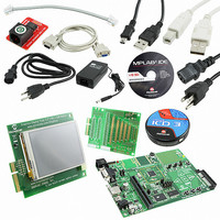
Contents
Dev Board, Display Board, 3 Bare Boards, MPLAB ICD-3, Cables, Power Supply
Processor To Be Evaluated
PIC24FJ256DA210
Data Bus Width
16 bit
Interface Type
RS-232, USB, Ethernet, SPI, UART
Operating Supply Voltage
9 V to 15 V
Silicon Manufacturer
Microchip
Core Architecture
PIC
Core Sub-architecture
PIC24
Silicon Core Number
PIC24F
Silicon Family Name
PIC24FJxxDAxxx
Lead Free Status / RoHS Status
Lead free / RoHS Compliant
For Use With/related Products
PIC24FJ256DA210
Lead Free Status / Rohs Status
Lead free / RoHS Compliant
Available stocks
Company
Part Number
Manufacturer
Quantity
Price
Company:

Part Number:
DV164039
Manufacturer:
MICROCHIP
Quantity:
12 000
Part Number:
DV164039
Manufacturer:
MICROCHIP/微芯
Quantity:
20 000


2010 Microchip Technology Inc.
4.4.1.2
The development board is equipped with five touch sensor inputs. These are multi-
plexed between three CTMU (Charge Time Measurement Unit) analog channels, as
shown in Table 4-4. The areas within the white border of each pad is the touch-sensitive
areas. Note that all three CTMU inputs must be enabled to use the entire pad.
TABLE 4-4:
To enable the CTMU Touch Pads:
1. To enable PAD1 (Figure 4-3, callout 1):
2. To enable PAD2 (Figure 4-3, callout 2):
3. To enable PAD3 (Figure 4-3, callout 3):
4.4.1.3
Pin RB5 can also be configured to read potentiometer R3. This selection is enabled by
setting JP15 to position RB5–POT. No other changes are required.
4.4.1.4
There are four user-defined LEDs on the development board.
LEDs D1, D2 and D3 (red) are multiplexed with the CTMU pads. They are individually
enabled when their corresponding CTMU pads are enabled, as described in
Section 4.4.1.2 “CTMU Touch Sense Inputs”.
LED D4 (red) is multiplexed with address line 17 of the parallel RAM and Flash mem-
ories. To use this LED, jumper JP11 must be set to position 1-2. Refer to
Section 4.4.5 “On-Board External Memory” for more information.
Note:
a) Set jumper JP13 to position PAD1–RG8
b) If installed, remove resistors R26 and R27
c) Populate resistor R25 with a
a) Set jumper JP14 to position PAD2–RE9
b) If installed, remove resistor R32
c) Populate resistor R31 with a
a) Set jumper JP15 to position PAD3–RB5
b) If installed, remove resistor R45
c) Populate resistor R41 with a
CTMU TOUCH SENSE INPUTS
ANALOG INPUT (POTENTIOMETER)
LED OUTPUTS
CTMU signals are connected to PIC24FJ256DA210 analog pins. Make
sure that the pins are set to analog pins using their corresponding ANSx
control bits. Refer to the “PIC24FJ256DA210 Family Data Sheet
(DS39969)” for details.
Touch Pad
RIGHT
DOWN
LEFT
CTMU TOUCH PAD COMBINATIONS
SEL
UP
Development Board Hardware
0
0
0
PAD1 (RG8)
resistor (default)
resistor (default)
resistor (default)
X
X
PAD2 (RE9)
X
X
X
DS51911A-page 37
PAD3 (RB5)
X
X
X
Related parts for DV164039
Image
Part Number
Description
Manufacturer
Datasheet
Request
R

Part Number:
Description:
Manufacturer:
Microchip Technology Inc.
Datasheet:
Part Number:
Description:
Manufacturer:
Microchip Technology Inc.
Datasheet:
Part Number:
Description:
Manufacturer:
Microchip Technology Inc.
Datasheet:
Part Number:
Description:
Manufacturer:
Microchip Technology Inc.
Datasheet:
Part Number:
Description:
Manufacturer:
Microchip Technology Inc.
Datasheet:
Part Number:
Description:
Manufacturer:
Microchip Technology Inc.
Datasheet:
Part Number:
Description:
Manufacturer:
Microchip Technology Inc.
Datasheet:
Part Number:
Description:
Manufacturer:
Microchip Technology Inc.
Datasheet: