DM240312 Microchip Technology, DM240312 Datasheet - Page 46
DM240312
Manufacturer Part Number
DM240312
Description
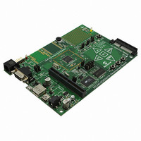
BOARD DEV PIC24FJ256DA210
Manufacturer
Microchip Technology
Series
dsPIC™r
Type
MCUr
Specifications of DM240312
Contents
Board
Processor To Be Evaluated
PIC24FJ256DA210
Data Bus Width
16 bit
Interface Type
RS-232, USB, Ethernet, SPI, UART
Operating Supply Voltage
9 V to 15 V
Silicon Manufacturer
Microchip
Core Architecture
PIC
Core Sub-architecture
PIC24
Silicon Core Number
PIC24F
Silicon Family Name
PIC24FJxxDAxxx
Kit Contents
Board
Lead Free Status / RoHS Status
Lead free / RoHS Compliant
For Use With/related Products
PIC24FJ256DA210
Lead Free Status / Rohs Status
Lead free / RoHS Compliant
Available stocks
Company
Part Number
Manufacturer
Quantity
Price
Company:

Part Number:
DM240312
Manufacturer:
Microchip Technology
Quantity:
135
Company:
Part Number:
DM240312
Manufacturer:
MICROCHIP
Quantity:
12 000


PIC24FJ256DA210 Development Board User’s Guide
DS51911A-page 46
To configure the 256 KByte address range (default):
1. Set jumper JP23 (callout 1) to position 1-2 (enables the parallel Flash memory).
2. Set JP11 (callout 2) to position 1-2 to connect PMA17 to LED D4 only, and use
3. If installed, remove resistor R63 (callout 4) (disconnects PMA18 signal from
To configure the 512 KByte address range:
1. Set jumper JP23 (callout 1) to position 1-2 (enables parallel Flash memory).
2. Set jumper JP11 (callout 2) to position 2-3 (connects PMA17 signal to Flash memory).
3. If installed, remove resistor R63 (callout 4) (disconnects PMA18 signal from Flash
To configure the 1024 KByte address range (assuming U5 is populated with a 1 Mbyte
device):
1. Set jumper JP23 to position 1-2 (callout 1) (enables parallel Flash memory).
2. Set jumper JP11 (callout 2) position 2-3 (connects PMA17 signal to Flash memory).
3. Populate resistor R63 (callout 4) with a
4. If installed, remove resistor R62 (callout 4) (disconnects PMA18 from the PICtail
4.4.6
A 120-pin PICtail Plus connector (J8) is provided on the PIC24FJ256DA210 Develop-
ment Board for expansion and integration of other solutions. At the time of this writing,
the following daughter boards are supported on the PIC24FJ256DA210 Development
Board:
• PICtail Daughter Board for SD & MMC Cards (AC164122)
• Ethernet PICtail Plus Daughter Board (AC164123)
• Fast 100 Mbps Ethernet PICtail Plus Daughter Board (AC164132)
• MRF24WB0MA PICtail Plus Daughter Board (AC164136-4)
• MRF49XA PICtail Plus Daughter Board (AC164137-1 or AC164137-2)
• Speech Playback PICtail Plus Daughter Board (AC164125)
• IrDA
Additional boards are planned to be available in the future. Users are encouraged to
check the Microchip web site periodically for more information.
To enable the support of multiple PICtail Plus Daughter Boards, the development board
maps selected I/Os to multiple PICtail Plus pins. In some cases, using certain daughter
boards may mean disabling some functionality on the development board. In general,
when the PICtail Plus connector is in use, these development board features are not
available:
1. All CTMU channels (most daughter boards).
2. EPMP Address lines PMA18 and PMA17. This reduces the accessible area of
3. PMP Byte Enable line PMBE1. This limits parallel Flash and SRAM devices to
4. USB OTG functionality (Device and Host modes are still available)
that microcontroller pin to control the LED.
Alternatively, remove jumper JP11 (disconnects PMA17 signal entirely).
Flash memory).
memory).
Flash memory).
Plus expansion port).
the parallel Flash device to 256 Kbytes, regardless of the device installed
Word accesses; in turn, this limits display modes to 16 bpp mode.
®
PICtail Plus Daughter Board (AC164124)
PICtail™ Plus Card Modular Expansion Connector
0
resistor (connects PMA18 signal to
2010 Microchip Technology Inc.
Related parts for DM240312
Image
Part Number
Description
Manufacturer
Datasheet
Request
R

Part Number:
Description:
Manufacturer:
Microchip Technology Inc.
Datasheet:
Part Number:
Description:
Manufacturer:
Microchip Technology Inc.
Datasheet:
Part Number:
Description:
Manufacturer:
Microchip Technology Inc.
Datasheet:
Part Number:
Description:
Manufacturer:
Microchip Technology Inc.
Datasheet:
Part Number:
Description:
Manufacturer:
Microchip Technology Inc.
Datasheet:
Part Number:
Description:
Manufacturer:
Microchip Technology Inc.
Datasheet:
Part Number:
Description:
Manufacturer:
Microchip Technology Inc.
Datasheet:
Part Number:
Description:
Manufacturer:
Microchip Technology Inc.
Datasheet: