DM240312 Microchip Technology, DM240312 Datasheet - Page 31
DM240312
Manufacturer Part Number
DM240312
Description
BOARD DEV PIC24FJ256DA210
Manufacturer
Microchip Technology
Series
dsPIC™r
Type
MCUr
Specifications of DM240312
Contents
Board
Processor To Be Evaluated
PIC24FJ256DA210
Data Bus Width
16 bit
Interface Type
RS-232, USB, Ethernet, SPI, UART
Operating Supply Voltage
9 V to 15 V
Silicon Manufacturer
Microchip
Core Architecture
PIC
Core Sub-architecture
PIC24
Silicon Core Number
PIC24F
Silicon Family Name
PIC24FJxxDAxxx
Kit Contents
Board
Lead Free Status / RoHS Status
Lead free / RoHS Compliant
For Use With/related Products
PIC24FJ256DA210
Lead Free Status / Rohs Status
Lead free / RoHS Compliant
Available stocks
Company
Part Number
Manufacturer
Quantity
Price
Company:

Part Number:
DM240312
Manufacturer:
Microchip Technology
Quantity:
135
Company:
Part Number:
DM240312
Manufacturer:
MICROCHIP
Quantity:
12 000


4.1
4.2
2010 Microchip Technology Inc.
INTRODUCTION
FUNCTIONAL OVERVIEW
Chapter 4. Development Board Hardware
This chapter provides a more detailed description of the hardware on the
PIC24FJ256DA210 Development Board, and the procedures on configuring its many
features. Topics covered include:
• Functional Overview
• General Hardware Features
• Setup and Configuration
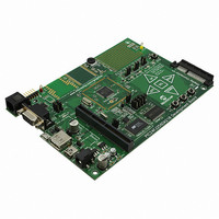
The development board is centered on the PIC24FJ256DA210 microcontroller which
integrates in a single package a graphic controller, a CTMU for touch-sensing applica-
tions, and a wide range of other peripherals.
The microcontroller’s Graphics module is capable of driving TFT, CSTN and MSTN dis-
plays in a number of sizes and color depths. Many display applications (up to 8 bpp in
QVGA) can be run from the microcontroller’s 96 KByte RAM buffer. For bigger displays
or higher color resolution, the microcontroller can directly interface with external RAM
devices for additional data storage. For non-volatile data storage, both serial and
parallel Flash memory devices are provided.
The built-in USB functionality can be configured to operate in Device mode, as a
stand-alone USB host, or as a USB On-The-Go (OTG) device. Host and OTG modes
can be additionally configured for different types of bus sensing and external regulator
support.
Push buttons, CTMU touch sensors and a potentiometer are provided for a variety of
user-defined inputs. These share three common I/Os on the microcontroller, along with
three LEDs, and are configured manually with jumpers.
A PICtail Plus edge connector is provided, allowing the development board to be used
with different compatible PICtail Plus daughter board. An RS-232 port is provided for
general purpose serial communications between the development board and a host
PC; this serial port can also be re-configured to be available through the PICtail Plus
connector.
Figure 4-1 shows the main components of the development board.
DEVELOPMENT BOARD
PIC24FJ256DA210
USER’S GUIDE
DS51911A-page 31
Related parts for DM240312
Image
Part Number
Description
Manufacturer
Datasheet
Request
R

Part Number:
Description:
Manufacturer:
Microchip Technology Inc.
Datasheet:
Part Number:
Description:
Manufacturer:
Microchip Technology Inc.
Datasheet:
Part Number:
Description:
Manufacturer:
Microchip Technology Inc.
Datasheet:
Part Number:
Description:
Manufacturer:
Microchip Technology Inc.
Datasheet:
Part Number:
Description:
Manufacturer:
Microchip Technology Inc.
Datasheet:
Part Number:
Description:
Manufacturer:
Microchip Technology Inc.
Datasheet:
Part Number:
Description:
Manufacturer:
Microchip Technology Inc.
Datasheet:
Part Number:
Description:
Manufacturer:
Microchip Technology Inc.
Datasheet: