MPC8313E-RDBB Freescale Semiconductor, MPC8313E-RDBB Datasheet - Page 21
MPC8313E-RDBB
Manufacturer Part Number
MPC8313E-RDBB
Description
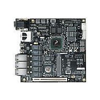
BOARD CPU 8313E VER 2.1
Manufacturer
Freescale Semiconductor
Series
PowerQUICC II™ PROr
Type
MPUr
Datasheets
1.MPC8313CZQAFFB.pdf
(100 pages)
2.MPC8313E-RDBB.pdf
(52 pages)
3.MPC8313E-RDBB.pdf
(2 pages)
Specifications of MPC8313E-RDBB
Contents
Board
Processor To Be Evaluated
MPC8xxx
Data Bus Width
32 bit
Interface Type
Ethernet, USB, JTAG, SPI, UART
Dimensions
170 mm x 170 mm
Operating Supply Voltage
3.3 V
For Use With/related Products
MPC8313E
Lead Free Status / RoHS Status
Lead free / RoHS Compliant


3.1
The COP connector allows the user to connect a COP/JTAG-based debugger to the MPC8313E RDB for
debugging.
3.2
The MPC8313E RDB has one 32-bit 3.3-V PCI expansion slot (P2) for an expansion card. The slot
connects AD15 for its device select signal. Only the 3.3-V PCI card is supported. Turn OFF power during
Freescale Semiconductor
Reference
D11
D16
D15
D14
D17
D13
D22
D21
D20
D3
D5
D2
D1
D4
COP Connector (P1)
PCI Slot (P2)
Table 4
On-chip USB PHY CTL1
12-V Indicator
5-V Indicator
3.3-V Indicator
2.5-V Indicator
5-V standby indicator
Programmable LED0 (Red)
Programmable LED1 (Yellow)
Programmable LED2 (Green)
Programmable LED3 (Green)
Programmable LED4 (Green)
Programmable LED5 (Green)
Programmable LED6 (Green)
Programmable LED7/LCD_EN (Green)
lists the pin assignments of the COP connector.
Table 3. Connectors, Jumpers, Switches, and LEDs (continued)
PowerQUICC™ MPC8313E Reference Design Board (RDB), Rev. 4
Pin
11
13
15
1
3
5
7
9
Table 4. COP Connector Pin Assignments
CKSTP_OUT
SRESET
HRESET
Signal
QREQ
TDO
TCK
TMS
TDI
Description
Pin
10
12
14
16
2
4
6
8
VDD_SENSE
CKSTP_IN
Signal
TRST
Connectors, Jumpers, Switches, and LEDs
GND
GND
NC
NC
NC
Section/Page
3.12/Page 27
—
—
—
—
—
—
21
Related parts for MPC8313E-RDBB
Image
Part Number
Description
Manufacturer
Datasheet
Request
R

Part Number:
Description:
Mpc8313e Powerquicc Ii Pro Processor
Manufacturer:
Freescale Semiconductor, Inc
Datasheet:

Part Number:
Description:
BOARD PROCESSOR
Manufacturer:
Freescale Semiconductor
Datasheet:

Part Number:
Description:
BOARD CPU 8313E VER 2.2
Manufacturer:
Freescale Semiconductor
Datasheet:
Part Number:
Description:
Microprocessors - MPU 8313 REV2.2 PB ENC EXT
Manufacturer:
Freescale Semiconductor
Datasheet:
Part Number:
Description:
Microprocessors - MPU 8313 REV2.2 PB W/ENC
Manufacturer:
Freescale Semiconductor
Datasheet:
Part Number:
Description:
Microprocessors - MPU 8313 REV2.2 PB NO EN EXT
Manufacturer:
Freescale Semiconductor
Datasheet:
Part Number:
Description:
Microprocessors - MPU 8313 REV2.2 PB NO ENC
Manufacturer:
Freescale Semiconductor
Datasheet:
Part Number:
Description:
Manufacturer:
Freescale Semiconductor, Inc
Datasheet:
Part Number:
Description:
Manufacturer:
Freescale Semiconductor, Inc
Datasheet:
Part Number:
Description:
Manufacturer:
Freescale Semiconductor, Inc
Datasheet:
Part Number:
Description:
Manufacturer:
Freescale Semiconductor, Inc
Datasheet:
Part Number:
Description:
Manufacturer:
Freescale Semiconductor, Inc
Datasheet:
Part Number:
Description:
Manufacturer:
Freescale Semiconductor, Inc
Datasheet:
Part Number:
Description:
Manufacturer:
Freescale Semiconductor, Inc
Datasheet:
Part Number:
Description:
Manufacturer:
Freescale Semiconductor, Inc
Datasheet: