TWR-MPC5125 Freescale Semiconductor, TWR-MPC5125 Datasheet - Page 3
TWR-MPC5125
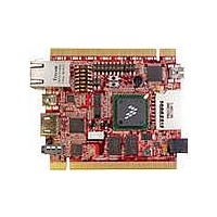
Manufacturer Part Number
TWR-MPC5125
Description
TOWER SYSTEM BOARD MPC5125
Manufacturer
Freescale Semiconductor
Type
MCUr
Specifications of TWR-MPC5125
Contents
Board
Processor To Be Evaluated
MPC5125
Data Bus Width
32 bit
Interface Type
Ethernet, USB, HDMI
Maximum Operating Temperature
+ 125 C
Minimum Operating Temperature
- 40 C
Silicon Manufacturer
Freescale
Core Architecture
Power Architecture
Core Sub-architecture
Power Architecture
Silicon Core Number
MPC5xxx
Silicon Family Name
MobileGT
Rohs Compliant
Yes
For Use With/related Products
Freescale Tower System
Lead Free Status / RoHS Status
Lead free / RoHS Compliant


Step-by-Step Installation Instructions
In this Quick Start Guide, you will learn how to set up the TWR-MPC5125
module and run the default demonstration software. The following
instructions are for Windows
provided, connect the HDMI port on the
TWR-MPC5125 to a DVI-D port on a
display monitor. (Alternatively, connect the
HDMI port to an HDMI port on a monitor.
Cable not provided.)
Note: DVI –to–VGA is not supported.
Quick Start Guide for TWR-MPC5125
STEP
1
Connect the HDMI cable
Using the HDMI-to-DVI-D cable
®
XP.
bridge to provide power
Power the board from a host computer
by plugging in the dual-port USB cable.
Insert the two Standard-A plugs into two
USB ports a host computer. Then insert
the Mini-B side of the cable into the
Mini-B connector (J19) which is next to
the SDHC card slot.
(Alternatively, the board can be powered
by a 5V barrel jack from a wall supply. The
supply must be a center-hot configuration
2.1 mm jack and the voltage must be 5V.
Cable not provided).
STEP
2
Connect the USB cable
for the Serial-to-USB
TOWER SYSTEM
Related parts for TWR-MPC5125
Image
Part Number
Description
Manufacturer
Datasheet
Request
R

Part Number:
Description:
K53N512CMD100 TWR Module
Manufacturer:
Freescale Semiconductor
Datasheet:
Part Number:
Description:
TWR-K53N512 Dev Kit
Manufacturer:
Freescale Semiconductor
Datasheet:

Part Number:
Description:
CONV DC/DC TRI OUT 5,15,-15V
Manufacturer:
Murata Power Solutions Inc
Datasheet:

Part Number:
Description:
CONV DC/DC TRI OUT 5,12,-12V
Manufacturer:
Murata Power Solutions Inc
Datasheet:

Part Number:
Description:
CONV DC/DC TRI OUT 5,15,-15V
Manufacturer:
Murata Power Solutions Inc
Datasheet:

Part Number:
Description:
LCD MODULE FOR TWR SYSTEM
Manufacturer:
Freescale Semiconductor
Datasheet:

Part Number:
Description:
DC/DC TH 11W 5-5/12V Triple A
Manufacturer:
Murata Power Solutions Inc
Datasheet:


Part Number:
Description:
TOWER SYSTEM PROTO
Manufacturer:
Freescale Semiconductor
Datasheet:

Part Number:
Description:
TOWER ELEVATOR BOARDS HARDWARE
Manufacturer:
Freescale Semiconductor
Datasheet:

Part Number:
Description:
TOWER SERIAL I/O HARDWARE
Manufacturer:
Freescale Semiconductor
Datasheet:

Part Number:
Description:
TOWER SYSTEM KIT MPC5125
Manufacturer:
Freescale Semiconductor
Datasheet:

Part Number:
Description:
TOWER SYSTEM BOARD K40X256
Manufacturer:
Freescale Semiconductor
Datasheet: