DEMOEM Freescale Semiconductor, DEMOEM Datasheet
DEMOEM
Specifications of DEMOEM


Related parts for DEMOEM


DEMOEM Summary of contents
Page 1
...
Page 2
Purchase Agreement P&E Microcomputer Systems, Inc. reserves the right to make changes without further notice to any products herein to improve reliability, function, or design. P&E Microcomputer Systems, Inc. does not assume any liability arising out of the application or ...
Page 3
... DEMOEM Base Board Features .................................................................... 2 2.2 On-Board Logic Analyzer ............................................................................... 7 2.3 On-Board Virtual USB Port............................................................................. 7 2.4 DEMOEM Daughter Card Features ............................................................... 8 2.5 DEMOEM Jumper/Connector Quick Reference............................................. 8 3 GETTING STARTED WITH THE DEMOEM................................................. 11 4 SYSTEM SETUP .......................................................................................... 11 4.1 Overview ...................................................................................................... 11 4.2 Operating System Requirements ................................................................ 12 4.3 Software Setup............................................................................................. 12 4.4 Quick Startup ...
Page 4
... Optional Jumpers For Various VDD And VSS ..............................................34 8 DEMOEM CODE DEVELOPMENT SOFTWARE......................................... 34 8.1 Using CodeWarrior With The DEMOEM.......................................................34 8.2 Using P&E Software With The DEMOEM.....................................................35 9 TRANSITIONING TO YOUR OWN TARGET ............................................... 35 9.1 Hardware Solutions At A Glance ..................................................................36 9.2 Working With P&E’s USB Multilink ...............................................................37 9.3 Working With P& ...
Page 5
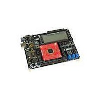
... MCF51EM256 and MCF51EM128 microcontrollers. It consists of a DEMOEM Base Board and a DCF51EM256 Daughter Card. P&E’s Embedded Multilink circuitry on the DEMOEM board allows the processor connected to the DEMOEM to be debugged and programmed via USB from a PC. In addition, the demo board can be powered using the USB bus. 1.2 ...
Page 6
... P&E Embedded Multilink Toolkit applications • P&E Embedded Multilink driver installation guide and resources 1.5 Handling Precautions Take care to handle the package contents, including the DEMOEM Base Board and DCF51EM256 Daughter Card manner such as to prevent electrostatic discharge. 2 HARDWARE FEATURES The DEMOEM is a demonstration and development system for Freescale’s MCF51EM256 microcontrollers. Application development is quick and easy using P& ...
Page 7
... Integrated P&E Embedded Multilink Circuitry • • • BDM Connector (6-pin Header) (not populated) • Jumpers (J39 and J40) to select programming the MCU daughter card or the MC9S08QE8 on the DEMOEM Power: • Power LED • Board power via the USB connection • ...
Page 8
... MCU_PORT header if the board is powered though the on-board regulator or USB Use circuit components recommended by crystal manufacturer and MCU data sheet. Footprint for jumpers to disable XTAL from MCU 0 ohm resistors in parallel with jumper footprints to connect XTAL circuit DEMOEM User Manual ...
Page 9
... Serial Communication: • IR interface (Tx and Rx). Connected with SCI1. (External circuitry DEMOEM User Manual Jumpers (J25) to configure front and back plane selection Optional crystal footprint on DCF51EM256 daughter card (not populated) Piezo buzzer for IRTC alarm Three Potentiometers 6 PWM outputs with low-pass filters in order to generate 60/50 Hz ...
Page 10
... Header pins for user connector or convenient monitoring of every serial port • Specifications: • • • • 6 Board Size 6.0 x 4.5 Daughter Card Size 2.0 x 2.1 Power Input: • USB Cable: 5VDC, 500mA max DC Power Jack: 2.1/5.5mm barrel connector, 6VDC Center Positive DEMOEM User Manual ...
Page 11
... DVD-ROM, displays the logic analyzer signals on a PC. 2.3 On-Board Virtual USB Port The DEMOEM board has a built-in virtual serial port which may be connected to the EM processor’s SCI RXD/TXD. This allows certain PC applications to be able to connect in a serial fashion to the microcontroller without the actual use of serial port hardware. The Terminal Window Utility, included in the P& ...
Page 12
... A top-mounted MCF51EM256 chip 2.5 DEMOEM Jumper/Connector Quick Reference Default Jumper Settings The following is a list of default jumper settings for DEMOEM board. The settings listed indicate the “on” (or installed) position. More detailed description of the jumper settings are available in Section 7 - JUMPER SETTINGS. ...
Page 13
... DEMOEM User Manual Default Jumper Settings J15 ALL ON J16 ALL ON J17 ALL OFF J18 ALL ON J19 Not Populated J20 Not Populated J21 1&2 J22 Not Populated J23 Not Populated J24 1&2 J25 2&4, 3&5 J26 ALL ON J27 ALL ON J28 ALL ON J29 ...
Page 14
... J38 ALL ON J39 1&2 J40 1&2 J41 ALL ON J42 1&2 J43 1&2 J44 1&2 QE8 Vdd IRTC VBAT Supply QE8 PWM to ADC Debug Reset EM/QE Debug BKGD EM/QE PTA LED Enable PTB0 IR Capacitor PTB0 IR Enable Piezo Buzzer Enable DEMOEM User Manual ...
Page 15
... GETTING STARTED WITH THE DEMOEM The DEMOEM is a low-cost board targeting quick microcontroller evaluation. Please refer to the DEMOEM Quick Start Guide and Labs for instructions on how to install software, connect the DEMOEM to your PC, and run quick demonstrations. 4 SYSTEM SETUP 4.1 Overview P& ...
Page 16
... To install the CodeWarrior Development Studio, follow the instructions on the DVD-ROM. 4.3.2 Installing P&E Resources Use the DEMOEM Resources in the DVD-ROM to access and install P&E resources for the DEMOEM. These materials are not required for operation. The DEMOEM Resources in the Getting Started DVD-ROM contains the following support materials: • ...
Page 17
... Quick Startup Only a few steps are required to get the DEMOEM up and running. Please reference the Quick Start Guide. 4.5 Hardware Setup 4.5.1 First-Time Connection The DEMOEM may be connected through a USB port. Connection steps are listed below in typical order: 1. Install the required software, as described in the previous section. ...
Page 18
... Click the “Finish” button to exit the current “Found New Hardware Wizard”. 6. Depending on the operating system, you may see the “Found New Hardware Wizard” dialog again to assist you with software installation for “PEMicro USB Serial Port (i1).” On Windows XP (SP2), the follow- ing dialog will appear: 14 DEMOEM User Manual ...
Page 19
... Figure 4-3: Found New Hardware Wizard Dialog ( Select the “Install the software automatically (Recommended)” option and click the “Next” button. 7. Windows will install the driver files to your system. At the end of the installation, the following dialog box will appear: DEMOEM User Manual 15 ...
Page 20
... Click the “Finish” button to exit the “Found New Hardware Wizard.” If the DEMOEM hardware interface driver is now properly installed on your system, the green USB LED (D1000) on the DEMOEM Base Board should be illuminated. In addition, if you turn on the system power of the DEMOEM you will see the red Power LED (D2) illuminate. 5 OPERATING MODES 5 ...
Page 21
... DEMOEM CODE DEVELOPMENT SOFTWARE for more information. 5.3 Run Mode The DEMOEM’s rich component list empowers it to perform a variety of tasks. Once an application is developed, debugged, and programmed properly into the EM internal flash memory, it can run with or without connecting to a host. 5.4 ...
Page 22
... PC. The logic analyzer data is displayed in real-time and each waveform may be paused, zoomed, and printed. To start using this application, please plug in a USB cable into the DEMOEM board. Once the USB and Power LEDs light up, indicating the proper enumeration on the USB port, click on the Open DEMO and Graph Pins button ...
Page 23
... DEMOEM Unsecure Application This application allows secure CFV1 and HCS08 microcontrollers to be unsecured. The Unsecure application will erase a secure device to make it unsecure. This application works with the DEMOEM board as well as other user hardware connected to the PC via the USB Multilink or Cyclone PRO hardware interfaces. ...
Page 24
... Port text box. Please select HCS08 or CFV1 from the Select Architecture drop down menu and press the Perform Unsecure button. The application will finish unsecuring and erasing the device shortly thereafter. This PC-based application is included on the DVD-ROM that accompanies the DEMOEM, and may also be found at: http://www.pemicro.com/fixedlinks/demotoolkit.cfm. 6.4 Serial Grapher Application This PC-based application is a generalized version that may be used with custom microcontroller code which transmits data in the correct format ...
Page 25
... The data format indicates whether the data is byte or word data. The graphical components automatically size their range depending upon the incoming data. This PC-based application is included on the DVD-ROM that accompanies the DEMOEM and may also be found at: http://www.pemicro.com/fixedlinks/demotoolkit.cfm. 6.4.1 Visual Components The Bar Graph has four separate bars and D ...
Page 26
... As can be seen in Data Format, each incoming data command affecting the graphing component must have new data for all four waveforms. An example graph is shown here: 22 Figure 6-4: Serial Grapher Bar Graph DEMOEM User Manual ...
Page 27
... CR (carriage return) and LF (line feed). The accepted commands are: WnnZnnYnnXnn The nn values are 00-FF and correspond in order to the data displayed on the following graph lines AnnBnnCnnDnn The nn values are 00-FF and correspond in order to the data displayed on the following bar graphs lines DEMOEM User Manual 23 ...
Page 28
... The on-board regulator can regulate the output to 3.3V. Power input is selected by using the J3, J4, and J24 headers. Select the USB port to supply microcontroller VDD. This is the default setting. Figure 7-1: Power Source Selection Header (J3) 24 DEMOEM User Manual ...
Page 29
... Virtual Serial Port The DEMOEM board has a built-in virtual serial port which may be connected to the EM processor’s SCI or SCI3 Rx and Tx. This allows certain PC applications to be able to connect in a serial fashion to the microcontroller without the actual use of serial port hardware. It can be enabled or disabled by installing or removing the jumpers of J7 and J8 ...
Page 30
... Note: The default connection is to the SCI3 signals. 7.4 SPI Port The DEMOEM board provides three headers for convenient access to SPI module signals: J11 for SPI1, J12 for SPI2, and J13 for SPI3. The signals are arranged as below: 26 Figure 7-5: RX_EN Header (J8) ...
Page 31
... Header J14 configures control signals for the EEPROM IC (U4). 7.6 LED Display Port The DEMOEM has 4 LEDs connected to signals PTE4, PTE5, PTA5, and PTA6 that may be driven by 5V. They can be enabled or disabled by installing or removing the corresponding jumpers, J15 & J41, in the LED_EN header. ...
Page 32
... Figure 7-11: LED Display Enable Header LED_EN (J41) 7.7 IR Interface 7.7.1 J16 - IR_EN Header The DEMOEM includes an infrared communications interface whose signals are connected with SCI1 and are jumper enabled by J16. 7.7.2 J42 - PTB0 IR Capacitor Connects a 0.1 uF bypass capacitor to PTB0. 7.7.3 J43 - PTB0 IR Enable Connects PTB0 to the IR circuitry ...
Page 33
... External Crystal Circuitry The DEMOEM design incorporates, but has not populated, a crystal circuit for XOSC2. Jumper 17 enables the EXTAL2 and XTAL2 signal connections when populated. Figure 7-15: External Crystal Circuitry CLK2_EN (J17) 7.9 P&E’s Input Capture Header 7.9.1 J18 - P&E’s Logic Analyzer Inputs IN0/IN1 The logic analyzer inputs are marked on one side of the J18 jumper. The inputs allow P& ...
Page 34
... Figure 7-16: Jumper Settings for Input Signals to P&E’s Embedded Multilink, P&E 7.10 LCD Module The DEMOEM brings all LCD signals to two 22x2 headers, J26 and J27. By default all jumpers are installed. Header 25 is used to demonstrate FP/BP selection. By default, LCD0 controls BP0 and LCD4 controls FP0. ...
Page 35
... J31. By default it is connected to a pulldown resistor. Figure 7-20: IRQ Pull-Up/Pull-Down Enable (J31) The DEMOEM board has a RESET button and LED enabled by Header J33. DEMOEM User Manual Figure 7-21: IRQ_EN (J32) 31 ...
Page 36
... QE8-Related Jumper Settings The DEMOEM incorporates a QE8 device, which obtains power from jumper J36. Its 6 PWM channels are connected via jumper J38 to DEMOEM ADC inputs. Its BKGD and Reset debugging signals are selected via jumpers J39 and J40. Please see the corresponding section for the header definition. ...
Page 37
... Debugging Signal Selection Headers 7.15 VBAT Header The DEMOEM provides a configurable connection from the coin-cell CR2032 battery to the IRTC supply pin, via jumper 37 jumper is installed, the cell battery will provide power to the VBAT pin of the daughter card MCU. DEMOEM User Manual ...
Page 38
... The DEMOEM includes P&E’s Embedded Multilink circuitry external hardware BDM tool is needed to debug and program the DEMOEM. A user only needs to connect the DEMOEM to their PC to start developing code for it. The DEMOEM package comes with an evaluation edition of Freescale’s CodeWarrior studio. In addition, P&E’s evaluation software for HCS08 and ColdFire® ...
Page 39
... TRANSITIONING TO YOUR OWN TARGET Once you have finished working with the DEMOEM and are ready to build your own target, you will need a hardware tool to allow you to develop using your own board. P&E’s USB Multilink and P&E’s Cyclone PRO offer two effective solutions, depending on your needs. Both work with Freescale’ ...
Page 40
... Compatible with Freescale’s ColdFireV1, HCS08, RS08, and HC(S)12(X) microcontroller families • Communication via USB, Serial, and Ethernet Ports • Multiple image storage • LCD screen menu interface 36 PC-Controlled and User-Controlled Stand-Alone Operation Interactive Programming via Host PC In-Circuit Debugging, Programming, and Testing DEMOEM User Manual ...
Page 41
... The USB Multilink Interface works with Codewarrior as well as P&E’s in-circuit debugger and flash programmer to allow debug and flash programming of the target processor. P&E’s USB Multilink Development Packages come with the USB Multilink Interface, as well as flash programming software, in-circuit debugging software, Windows IDE, and register file editor. DEMOEM User Manual 37 ...
Page 42
... The Cyclone PRO also functions as a full-featured debug interface, and is supported by Freescale’s CodeWarrior as well as development software from P&E. P&E’s Cyclone PRO is also available bundled with additional software as part of various Development Packages. In addition to the Cyclone PRO, these 38 Figure 9-2: P&E’s Cyclone PRO DEMOEM User Manual ...
Page 43
... DEMOEM hardware. If this dialog indicates that the DEMOEM hardware is not connected to the PC, the first step is to make sure that the DEMOEM hardware is connected to the PC via a USB 2.0 high-speed cable connected, unplug and then plug in the USB cable on the DEMOEM board and click refresh in the connection assistant ...
Page 44
... This may give some indication of what the problem is. (D) Using a USB Hub The DEMOEM is a high-power USB device USB Hub is used, it must be a self-powered hub (i.e., with its own power supply). If the Hub is not self- powered the DEMOEM will not work. In general, USB ports located directly on the PC are high-power (self-powered) ports ...
Page 45
... If you are unable to disable the WinDriver system driver in the above fashion, you can delete the file c:\windows\system32\windrvr6.sys and then reboot your machine. You should then re-run the installer and complete the procedure. Reboot your machine after the installation has finished. DEMOEM User Manual 41 ...
Page 46
... DEMOEM User Manual ...
Page 47
...