C8051F996DK Silicon Laboratories Inc, C8051F996DK Datasheet - Page 14
C8051F996DK
Manufacturer Part Number
C8051F996DK
Description
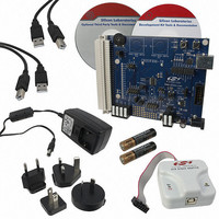
KIT DEV FOR C8051F996
Manufacturer
Silicon Laboratories Inc
Type
MCUr
Datasheets
1.C8051F996DK.pdf
(24 pages)
2.C8051F996DK.pdf
(2 pages)
3.C8051F996DK.pdf
(4 pages)
4.C8051F996DK.pdf
(322 pages)
Specifications of C8051F996DK
Contents
Board, Batteries, Cables, CDs, Debug Adapter, Documentation, Power Adapter
Processor To Be Evaluated
C8051F996
Processor Series
C8051F98x
Interface Type
USB
Operating Supply Voltage
3 V
Lead Free Status / RoHS Status
Lead free / RoHS Compliant
For Use With/related Products
C8051F996
Lead Free Status / Rohs Status
Lead free / RoHS Compliant
Other names
336-1963


C8051F996-DK
7.2. Target Board Power Options and Current Measurement
The C8051F996 Target Board supports three power options, selectable by the three-way header (J10/J11). Power
to the MCU may be switched on/off using the power switch (SW5). The power options are described in the
paragraphs below.
7.2.1. Wall Power
When the J10/J11 three-way header is set to WALL_PWR, the C8051F996 Target Board may be powered from the
following power sources:
All the three power sources are ORed together using reverse-biased diodes (D1, D2, D3), eliminating the need for
headers to choose between the sources. The target board will operate as long as any one of the power sources is
present. The ORed power is regulated to a 3.3 V dc voltage using a LDO regulator (U2). The output of the regulator
powers the +3 VD net on the target board. The VBAT supply net on the target board is powered directly from the
+3 VD net.
7.2.2. AAA Battery
When the J10/J11 three-way header is set to AAA_BAT, the C8051F996 Target Board is powered from the series
combination of the AAA batteries inserted in BH1 and BH2.
7.2.3. Coin Cell Battery
When the J10/J11 three-way header is set to COIN_CELL, the C8051F996 Target Board may be powered from a
3 V Lithium (CR2032) coin cell inserted in BH3.
7.2.4. Measuring Current
The header (J17) and terminal block (H2) provide a way to measure the total supply current flowing from the power
supply source to the MCU. The measured current does not include any current from the PWR LED (DS2) or the
quiescent current from the power supply; however, it does include the current used by any LEDs powered from the
VDD supply net or sourced through a GPIO pin. See the target board schematic in Figure 10 through Figure 12 for
additional information.
14
9 VDC power using the ac to dc power adapter (P2)
5 VDC USB VBUS power from PC via the USB Debug Adapter (J9)
5 VDC USB VBUS power from PC via the CP2103 USB connector (P3)
(J10, J11, J17, H2, P2, P3, SW5)
AAA_BAT
AAA_BAT
AAA_BAT
COIN_CELL
WALL_PWR
COIN_CELL
WALL_PWR
COIN_CELL
WALL_PWR
Rev. 0.1
J11
J11
J11
PWR
PWR
PWR
Related parts for C8051F996DK
Image
Part Number
Description
Manufacturer
Datasheet
Request
R

Part Number:
Description:
SMD/C°/SINGLE-ENDED OUTPUT SILICON OSCILLATOR
Manufacturer:
Silicon Laboratories Inc
Part Number:
Description:
Manufacturer:
Silicon Laboratories Inc
Datasheet:
Part Number:
Description:
N/A N/A/SI4010 AES KEYFOB DEMO WITH LCD RX
Manufacturer:
Silicon Laboratories Inc
Datasheet:
Part Number:
Description:
N/A N/A/SI4010 SIMPLIFIED KEY FOB DEMO WITH LED RX
Manufacturer:
Silicon Laboratories Inc
Datasheet:
Part Number:
Description:
N/A/-40 TO 85 OC/EZLINK MODULE; F930/4432 HIGH BAND (REV E/B1)
Manufacturer:
Silicon Laboratories Inc
Part Number:
Description:
EZLink Module; F930/4432 Low Band (rev e/B1)
Manufacturer:
Silicon Laboratories Inc
Part Number:
Description:
I°/4460 10 DBM RADIO TEST CARD 434 MHZ
Manufacturer:
Silicon Laboratories Inc
Part Number:
Description:
I°/4461 14 DBM RADIO TEST CARD 868 MHZ
Manufacturer:
Silicon Laboratories Inc
Part Number:
Description:
I°/4463 20 DBM RFSWITCH RADIO TEST CARD 460 MHZ
Manufacturer:
Silicon Laboratories Inc
Part Number:
Description:
I°/4463 20 DBM RADIO TEST CARD 868 MHZ
Manufacturer:
Silicon Laboratories Inc
Part Number:
Description:
I°/4463 27 DBM RADIO TEST CARD 868 MHZ
Manufacturer:
Silicon Laboratories Inc
Part Number:
Description:
I°/4463 SKYWORKS 30 DBM RADIO TEST CARD 915 MHZ
Manufacturer:
Silicon Laboratories Inc
Part Number:
Description:
N/A N/A/-40 TO 85 OC/4463 RFMD 30 DBM RADIO TEST CARD 915 MHZ
Manufacturer:
Silicon Laboratories Inc
Part Number:
Description:
I°/4463 20 DBM RADIO TEST CARD 169 MHZ
Manufacturer:
Silicon Laboratories Inc