DEMO9S08AW60E Freescale Semiconductor, DEMO9S08AW60E Datasheet - Page 13
DEMO9S08AW60E
Manufacturer Part Number
DEMO9S08AW60E
Description
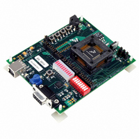
DEMO BOARD FOR MC9S08AW60
Manufacturer
Freescale Semiconductor
Type
MCUr
Datasheets
1.DEMO9S08AW60E.pdf
(24 pages)
2.DEMO9S08AW60E.pdf
(4 pages)
3.DEMO9S08AW60E.pdf
(5 pages)
Specifications of DEMO9S08AW60E
Contents
Board
Processor To Be Evaluated
MC9S08AW60
Interface Type
RS-232, USB
Silicon Manufacturer
Freescale
Core Architecture
HCS08
Core Sub-architecture
HCS08
Silicon Core Number
MC9S08
Silicon Family Name
S08AW
Rohs Compliant
Yes
For Use With/related Products
MC9S08AW60
Lead Free Status / RoHS Status
Contains lead / RoHS non-compliant


1.8.1 Integrated BDM
1.8.2 BDM Header
1.8.3 Socketed MCU
Freescale Semiconductor
alone BDM interface available (J32). This header is non-populated in the
default configuration and can be installed by the user if needed.
The DEMO9S08AW60E features an integrated USB-BDM debugger from
P&E Microcomputer Systems. All necessary signals are provided via the
integrated debugger. A USB type B connector (J33) provides the connection
between the DEMO9S08AW60E and your host PC.
The integrated debugger provides the DEMO9S08AW60E with power
eliminating the need to power the board externally. Power is derived from the
USB bus, therefore total current consumption should not exceed 500mA.
Excessive current drain will violate the USB spec and damage to your Host
PC’s USB hub or the DEMO9S08AW60E could occur.
J32 is the stand alone BDM header. Use of this port requires the user to solder
a 2 x 6 100 mil center header on the board. The pinout is as follows:
The MC9S08AW60 silicon is socketed on the DEMO9S08AW60E board. This
socket is an open top, spring actuated, 0.8mm pitch socket. It is made by Wells
Electronics, part number 7314-064-0-08. Before connecting power to the demo
board the silicon should be installed in this socket. Using your thumb and index
finger, press down on the socket until it is fully actuated. Place the silicon in the
socket with a vacuum pen or other chip lifting device. Pin 1 of the silicon
(denoted by an indented dot) should be in the bottom left hand corner, towards
the USB connector J33. Release the socket. The MC9S08AW60 silicon should
be centered within the socket and firmly held in place.
DEMO9S08AW60E User’s Guide, Rev. 0.3
Table 1-2 BDM Connector (J32) Pinout
BKGD
NC
NC
1
3
5
2
4
6
RESET_B
GND
VDD
13
Related parts for DEMO9S08AW60E
Image
Part Number
Description
Manufacturer
Datasheet
Request
R

Part Number:
Description:
Manufacturer:
Freescale Semiconductor, Inc
Datasheet:
Part Number:
Description:
Manufacturer:
Freescale Semiconductor, Inc
Datasheet:
Part Number:
Description:
Manufacturer:
Freescale Semiconductor, Inc
Datasheet:
Part Number:
Description:
Manufacturer:
Freescale Semiconductor, Inc
Datasheet:
Part Number:
Description:
Manufacturer:
Freescale Semiconductor, Inc
Datasheet:
Part Number:
Description:
Manufacturer:
Freescale Semiconductor, Inc
Datasheet:
Part Number:
Description:
Manufacturer:
Freescale Semiconductor, Inc
Datasheet:
Part Number:
Description:
Manufacturer:
Freescale Semiconductor, Inc
Datasheet:
Part Number:
Description:
Manufacturer:
Freescale Semiconductor, Inc
Datasheet:
Part Number:
Description:
Manufacturer:
Freescale Semiconductor, Inc
Datasheet:
Part Number:
Description:
Manufacturer:
Freescale Semiconductor, Inc
Datasheet:
Part Number:
Description:
Manufacturer:
Freescale Semiconductor, Inc
Datasheet:
Part Number:
Description:
Manufacturer:
Freescale Semiconductor, Inc
Datasheet:
Part Number:
Description:
Manufacturer:
Freescale Semiconductor, Inc
Datasheet:
Part Number:
Description:
Manufacturer:
Freescale Semiconductor, Inc
Datasheet: