DEMO9S08AW60E Freescale Semiconductor, DEMO9S08AW60E Datasheet
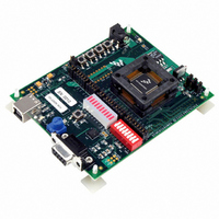
DEMO BOARD FOR MC9S08AW60

DEMO9S08AW60E

Manufacturer Part Number
DEMO9S08AW60E
Description
DEMO BOARD FOR MC9S08AW60
Manufacturer
Freescale Semiconductor
Type
MCUr

Specifications of DEMO9S08AW60E

Contents
Board
Processor To Be Evaluated
MC9S08AW60
Interface Type
RS-232, USB
Silicon Manufacturer
Freescale
Core Architecture
HCS08
Core Sub-architecture
HCS08
Silicon Core Number
MC9S08
Silicon Family Name
S08AW
Rohs Compliant
Yes
For Use With/related Products
MC9S08AW60
Lead Free Status / RoHS Status
Contains lead / RoHS non-compliant
Freescale Semiconductor
Quick Start Guide
Introduction and Default Settings
This guide will walk you through how to connect the DEMO9S08AW60E board to your PC, install
the correct version of CodeWarrior Development Studio, run the DEMO9S08AW60_TEST
program, and how to program the board with the DEMO9S08AW60_APP source code. The
source code for DEMO9S08AW60_TEST is provided on the included documentation CD in the
"Examples" folder.
Below are diagrams of the default settings for the DEMO9S08AW60E demo board. Black blocks
indicate the "on" or "installed" position of jumpers. Please check these settings before continuing.
Install the MC9S08AW60 Silicon
To protect the MC9S08AW60 silicon it is shipped in a chip case and needs to be installed in the
socket U3. Open the chip case and lift the silicon using a vacuum pen or other chip lifting device.
Using your thumb and index finger, press down on two corners of the socket U3 until it is
completely accuated. Place the MC9S08AW60 silicon in the center of the socket with pin 1 in the
bottom left hand corner, towards the USB connector J33. Pin 1 on the MC9S08AW60 silicon is
indicated by an indented dot. Release the socket. The MC9S08AW60 silicon should be centered
within the socket and firmly held in place.
© Freescale Semiconductor, Inc., 2006. All rights reserved.
DEMO9S08AW60E Quick Start Guide
5V
3V
W1
1
2
PTF0
3
1
J16
USB
EXT
PTF1
J17
W2
PTF2
J18
3
1
PTF3
J19
P_IO_5V
W3
PTF4
J20
2
1
Figure -1 DEMO9S08AW60E Default Settings
PTF5
W4
J21
DIS
PTF6
3
J22
PTF7
EN
J23
1
1
2
PTD0
J3
PTA0
J24
PTD1
J4
PTA1
J25
PTC4
PTA2
J5
J26
PTD4
PTA3
J6
J27
PTD5
PTA4
J7
J28
PTD6
PTA5
J29
J8
PTD7
PTA6
J9
J30
PTA7
J31
PTD2
J10
PTD3
J11
PTC2
J12
DEMO9S08AW60EUM
PTC6
J13
PTE0
Rev. 0.4, 01/2006
J14
PTE1
J15

Related parts for DEMO9S08AW60E

DEMO9S08AW60E Summary of contents

Page 1

... DEMO9S08AW60E Quick Start Guide Introduction and Default Settings This guide will walk you through how to connect the DEMO9S08AW60E board to your PC, install the correct version of CodeWarrior Development Studio, run the DEMO9S08AW60_TEST program, and how to program the board with the DEMO9S08AW60_APP source code. The source code for DEMO9S08AW60_TEST is provided on the included documentation CD in the " ...

Page 2

... Quick Start Guide. You must have administrator privileges to install CodeWarrior. Run the DEMO9S08AW60_TEST Program The DEMO9S08AW60E is shipped with the AW60_TEST program stored in on-chip FLASH memory. You may view the source code for this program by accessing the "AW60_TEST.zip" file on the included documentation CD (located in the "Examples" folder). ...

Page 3

... Values will be displayed in the terminal window based on the amount of light sensed by the photocell IC (U4). Vary the amount of light available to the photocell and watch the values change. Press SW4 when you are ready to move on to the accelerometer demo. Freescale Semiconductor DEMO9S08AW60E Quick Start Guide, Rev. 0.4 3 ...

Page 4

... Two columns of values will be displayed in the terminal window. The first is the X output of the accelerometer (U5) the second is the Y output. Move the DEMO9S08AW60E in the X and Y directions to see the values change. Press SW1 to complete the demo. Troubleshooting VDD LED does not turn on - Make sure jumper W2 is set to the USB (2-3) position - Make sure the USB drivers (located on the CodeWarrior 5 ...

Related keywords