DEMO908QC16 Freescale Semiconductor, DEMO908QC16 Datasheet - Page 11
DEMO908QC16
Manufacturer Part Number
DEMO908QC16
Description
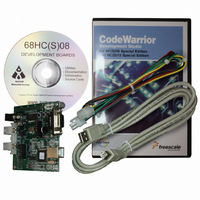
BOARD DEMO FOR MC908QC16
Manufacturer
Freescale Semiconductor
Type
MCUr
Specifications of DEMO908QC16
Contents
Board, Cable, CD
Processor To Be Evaluated
MC908QC16
Data Bus Width
8 bit
Interface Type
RS-232, USB
Silicon Manufacturer
Freescale
Core Architecture
HC08
Core Sub-architecture
HC08
Silicon Core Number
MC68HC908
Silicon Family Name
HC08Q
Kit Contents
Board
Rohs Compliant
No
For Use With/related Products
MC908QC16
Lead Free Status / RoHS Status
Contains lead / RoHS non-compliant


D E M O 9 0 8 Q C 1 6
J U N E
2 0 ,
2 0 0 5
POWER
The DEMO908QC16 is designed to be powered from the USB_MON08 debugger during appli-
cation development. A 2.0mm barrel connector is available to support LIN functionality and for
stand-alone operation. As an added feature, the board may source power through connector
J1 OR supply power to external circuitry connected to J1.
The integrated MON08 debugger simplifies application development by eliminating the need
for and external MON08 cable. During application development, the board draws power from
the USB bus through the integrated USB-MON08 connector. Total current consumption, of the
board and connected circuitry, must be limited to less than 500mA. Excessive current drain
will cause the USB bus to disconnect and may damage the target board or the host PC. USB
bus violations may also cause the host PC to reboot sporadically.
A 2.0mm barrel connector input has been provided to support LIN functionality and allow
stand-alone operation. Voltage input at this connector must be limited to between +7V and
+18V. An LDO voltage regulator at VR1 converts the input voltage to the +5V rail on the target
board. VR1 will shut down if the connected circuit draws excessive current or over-heats.
Stand-alone operation is supported though connector J1 but power input on this connector will
not support LIN functionality. Use caution when powering the target board from connector J1.
No protection is applied on this power input
CAUTION: J1 power input connects directly to the voltage rails on the board. Power input must
be regulated, 5VDC.
POWER SELECT
Power may be applied to the board through the integrated USB-MON08 circuitry, a 2.0mm bar-
rel connector, or through connector J1. Two option headers configure power routing on the
target board, PWR_SEL and VX_EN.
PWR_SEL
The PWR_SEL option header selects power input from either the integrated USB-MON08 de-
bugger or from the on-board voltage regulator. Pin 1 connects to the power output from the
integrated BDM. Pin 3 connects to the on-board voltage regulator output. Pin 2 provides
power to the target board voltage rail. Figure 3 below shows the PWR_SEL header selection
options.
Power from the integrated BDM is drawn from the USB bus and is limited to 500mA. Exces-
sive current drain will violate the USB specification and will cause the USB bus to disengage.
The host PC may also spontaneously reboot.
The on-board voltage regulator (VR1) accepts power input through a 2.0mm barrel connector
(PWR). Input voltage should be limited to between +7V to +18V. A voltage regulator at VR1
provides a +5V fixed output limited to 250mA. Over-temperature and over-current limit built
into the voltage regulator provides protection from excessive stresses. Use caution when at-
11
Related parts for DEMO908QC16
Image
Part Number
Description
Manufacturer
Datasheet
Request
R

Part Number:
Description:
Manufacturer:
STMicroelectronics
Datasheet:

Part Number:
Description:
DEMO BOARD FOR HMC6042/HMC1041Z
Manufacturer:
Honeywell Microelectronics & Precision Sensors

Part Number:
Description:
DEMO BOARD FOR HMC1042L/HMC1041Z
Manufacturer:
Honeywell Microelectronics & Precision Sensors
Datasheet:

Part Number:
Description:
KIT DEMO 4 SENSOR CHAN RS232
Manufacturer:
VTI Technologies
Datasheet:


Part Number:
Description:
DEMO: DC Power Supply, 32 Volts, 3 Amps
Manufacturer:
Tektronix
Part Number:
Description:
DEMO: Programmable DC Power Supply, 32 Volts, 3 Amps
Manufacturer:
Tektronix

Part Number:
Description:
Manufacturer:
Freescale Semiconductor, Inc
Datasheet:
Part Number:
Description:
Manufacturer:
Freescale Semiconductor, Inc
Datasheet:
Part Number:
Description:
Manufacturer:
Freescale Semiconductor, Inc
Datasheet:
Part Number:
Description:
Manufacturer:
Freescale Semiconductor, Inc
Datasheet:
Part Number:
Description:
Manufacturer:
Freescale Semiconductor, Inc
Datasheet:
Part Number:
Description:
Manufacturer:
Freescale Semiconductor, Inc
Datasheet:
Part Number:
Description:
Manufacturer:
Freescale Semiconductor, Inc
Datasheet:
Part Number:
Description:
Manufacturer:
Freescale Semiconductor, Inc
Datasheet: