DEMO9S08QG8E Freescale Semiconductor, DEMO9S08QG8E Datasheet - Page 14
DEMO9S08QG8E
Manufacturer Part Number
DEMO9S08QG8E
Description
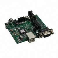
BOARD DEMO FOR MC9S08QG8
Manufacturer
Freescale Semiconductor
Type
MCUr
Specifications of DEMO9S08QG8E
Contents
Board
Processor To Be Evaluated
MC9S08QG8
Data Bus Width
8 bit
Interface Type
RS-232, USB
Silicon Manufacturer
Freescale
Core Architecture
HCS08
Core Sub-architecture
HCS08
Silicon Core Number
MC9S08
Silicon Family Name
S08QG
Kit Contents
MC9S08QG8 Board, Software, Cables, Connectors
Rohs Compliant
Yes
For Use With/related Products
MC9S08QG4, MC9S08QG8
Lead Free Status / RoHS Status
Lead free / RoHS Compliant
Available stocks
Company
Part Number
Manufacturer
Quantity
Price
Company:

Part Number:
DEMO9S08QG8E
Manufacturer:
Freescale Semiconductor
Quantity:
135


OPERATING MODES
The APS08QG8SLK board operates in two basic modes Run Mode, or Debug Mode. Run
Mode supports user application operation from Power-On or Reset. Debug Mode supports the
development and debug of applications via the BDM_PORT. See the related sections below
for quickly starting the board in the desired mode of operation.
The board has been preloaded with a demonstration program that operates in the Run Mode.
The VDD LED is lit when power is applied to the board and the PWR_SEL option header is set
correctly.
RUN Mode
Run mode allows the user application to execute when power is applied to the board or the
RESET button is pressed. Use the following settings to configure the APS08QG8SLK board
for RUN Mode using the USB bus to power the board. See the POWER section below for
details on configuring the board for alternate power input.
1. Connect a serial cable (not included) between the board and a host PC if needed.
2. Connect auxiliary equipment to board if needed.
3. Configure the board option jumpers as shown.
Table 3: Run Mode Setup
4. Connect the USB cable to an open USB port on the host PC and attach to the USB port on
Debug Mode
Debug Mode supports application development and debug using the HCS08/HC(S)12
background debug mode (BDM). Background mode is accessible using either the integrated
USB-BDM or an external HCS08/HC(S)12 BDM cable. Use of the integrated BDM requires
only a host PC with an available USB port and an A/B USB cable. The USB cable used must
be USB 2.0 compliant. A 6-pin BDM_PORT header supports the use of an external BDM
cable. This header is not installed in default configurations. The steps below describe using
the integrated USB-BDM. See the POWER section below for details on configuring the board
for alternate power input.
1. Connect a serial cable (not included) between the board and a host PC if needed.
14
the target board.
application will begin to execute.
PWR_SEL
COM_EN
VX_EN
USER_EN
The USB, USB_PWR, and VDD LEDs will light and the loaded
Set to VB
Set to PTA4
ON if required
ALL ON
Freescale Semiconductor
Related parts for DEMO9S08QG8E
Image
Part Number
Description
Manufacturer
Datasheet
Request
R

Part Number:
Description:
Manufacturer:
Freescale Semiconductor, Inc
Datasheet:
Part Number:
Description:
Manufacturer:
Freescale Semiconductor, Inc
Datasheet:
Part Number:
Description:
Manufacturer:
Freescale Semiconductor, Inc
Datasheet:
Part Number:
Description:
Manufacturer:
Freescale Semiconductor, Inc
Datasheet:
Part Number:
Description:
Manufacturer:
Freescale Semiconductor, Inc
Datasheet:
Part Number:
Description:
Manufacturer:
Freescale Semiconductor, Inc
Datasheet:
Part Number:
Description:
Manufacturer:
Freescale Semiconductor, Inc
Datasheet:
Part Number:
Description:
Manufacturer:
Freescale Semiconductor, Inc
Datasheet:
Part Number:
Description:
Manufacturer:
Freescale Semiconductor, Inc
Datasheet:
Part Number:
Description:
Manufacturer:
Freescale Semiconductor, Inc
Datasheet:
Part Number:
Description:
Manufacturer:
Freescale Semiconductor, Inc
Datasheet:
Part Number:
Description:
Manufacturer:
Freescale Semiconductor, Inc
Datasheet:
Part Number:
Description:
Manufacturer:
Freescale Semiconductor, Inc
Datasheet:
Part Number:
Description:
Manufacturer:
Freescale Semiconductor, Inc
Datasheet:
Part Number:
Description:
Manufacturer:
Freescale Semiconductor, Inc
Datasheet: