XE8000EV101 Semtech, XE8000EV101 Datasheet - Page 105
XE8000EV101
Manufacturer Part Number
XE8000EV101
Description
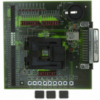
EVAL BOARD FOR XE8801AMI027LF
Manufacturer
Semtech
Type
MCUr
Specifications of XE8000EV101
Contents
Fully Assembled Evaluation Board
For Use With/related Products
XE88LC01AMI027
Lead Free Status / RoHS Status
Contains lead / RoHS non-compliant


16.8.3
16.8.3.1
The integral non-linearity depends on the selected gain configuration. First of all, the non-linearity of the ADC (all
PGA stages bypassed) is shown in Figure 16-8.
The different PGA stages have been designed to find the best compromise between the noise performance, the
integral non-linearity and the power consumption. To obtain this, the first stage has the best noise performance and
the third stage the best linearity performance. For large input signals (small PGA gains, i.e. up to about 50), the noise
added by the PGA is very small with respect to the input signal and the second and third stage of the PGA should be
used to get the best linearity. For small input signals (large gains, i.e. above 50), the noise level in the PGA is
important and the first stage of the PGA should be used.
The following figures give the non-linearity for different gain settings of the PGA, selecting the appropriate stage to
get the best noise and linearity performance. Figure 16-9 shows the non-linearity when the third stage is used with a
gain of 1. It is of course not very useful to use the PGA with a gain of 1 unless it is used to compensate offset. By
increasing the gain, the integral non-linearity becomes even smaller since the signal in the amplifiers reduces.
Figure 16-10 shows the non-linearity for a gain of 2. Figure 16-11 shows the non-linearity for a gain of 5. Figure
16-12 shows the non-linearity for a gain of 10. By comparing these figures to Figure 16-8, it can be seen that the
third stage of the PGA does not add significant integral non-linearity.
Figure 16-13 shows the non-linearity for a gain of 20 and Figure 16-14 shows the non-linearity for a gain of 50. In
both cases the PGA2 is used at a gain of 10 and the remaining gain is realized by the third stage. It can be seen
again that the second stage of the PGA does not add significant non-linearity.
For gains above 50, the first stage PGA1 should be selected in stead of PGA2. Although the non-linearity in the first
stage of the PGA is larger than in stage 2 and 3, the gain in stage 3 is now sufficiently high so that the non-linearity
of the first stage does become negligible as is shown in Figure 16-15 for a gain of 100. Therefor, the first stage is
preferred over the second stage since it has less noise.
Increasing the gain further up to 1000 will further increase the linearity since the signal becomes very small in the
first two stages. The signal is full scale at the output of stage 3 and as shown in Figure 16-9 to Figure 16-12, this
stage has very good linearity.
© Semtech 2005
Linearity
Integral non-linearity
Figure 16-8 Integral non-linearity of the ADC (PGA disabled, reference voltage of 4.8V)
16-20
XE8801A – SX8801R
www.semtech.com
Related parts for XE8000EV101
Image
Part Number
Description
Manufacturer
Datasheet
Request
R

Part Number:
Description:
EVALUATION BOARD
Manufacturer:
Semtech
Datasheet:
Part Number:
Description:
EVALUATION BOARD
Manufacturer:
Semtech
Datasheet:
Part Number:
Description:
VOLTAGE SUPPRESSOR, TRANSIENT SEMTECH
Manufacturer:
Semtech
Datasheet:

Part Number:
Description:
HIGH VOLTAGE CAPACITORS MONOLITHIC CERAMIC TYPE
Manufacturer:
Semtech Corporation
Datasheet:
Part Number:
Description:
EZ1084CM5.0 AMP POSITIVE VOLTAGE REGULATOR
Manufacturer:
Semtech Corporation
Datasheet:
Part Number:
Description:
3.0 AMP LOW DROPOUT POSITIVE VOLTAGE REGULATORS
Manufacturer:
Semtech Corporation
Datasheet:
Part Number:
Description:
Manufacturer:
Semtech Corporation
Datasheet:
Part Number:
Description:
RailClamp Low Capacitance TVS Diode Array
Manufacturer:
Semtech Corporation
Datasheet:
Part Number:
Description:
Manufacturer:
Semtech Corporation
Datasheet:
Part Number:
Description:
Manufacturer:
Semtech Corporation
Datasheet:
Part Number:
Description:
Manufacturer:
Semtech Corporation
Datasheet:
Part Number:
Description:
Manufacturer:
Semtech Corporation
Datasheet: