EDB9315A-Z Cirrus Logic Inc, EDB9315A-Z Datasheet - Page 8
EDB9315A-Z
Manufacturer Part Number
EDB9315A-Z
Description
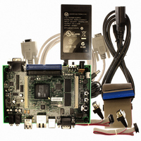
KIT DEVELOPMENT EP9315 ARM9
Manufacturer
Cirrus Logic Inc
Type
MCUr
Specifications of EDB9315A-Z
Contents
Development Board, Software, Schematics, Gerbers, Power Supply, Cable and Documentation
Silicon Manufacturer
Cirrus Logic
Core Architecture
ARM
Core Sub-architecture
ARM9
Features
Serial EEPROM Interface, 10/100 Mbps Ethernet, External Battery Backed RTC
Silicon Family Name
ARM
Silicon Core Number
EP9315
Rohs Compliant
Yes
Lead Free Status / RoHS Status
Lead free / RoHS Compliant
For Use With/related Products
EP9312, EP9315
Lead Free Status / RoHS Status
Lead free / RoHS Compliant, Lead free / RoHS Compliant
Other names
598-1144
EDB9315A
EDB9315A


EDB9315A
Technical Reference Manual
3. Getting Started
3.1 Before you Begin...
The developer will find it useful to have some additional hardware not provided in the EDB9315A kit.
Items such as a USB mouse, USB keyboard, VGA monitor and cable, and a set of powered speakers
can make using the EDB9315A and the software installed on the board more enjoyable.
3.2 Attaching Cables
Before attaching cables to the board make sure you know where pin 1 for each of the connectors is
located. Most connectors are keyed. However, some connectors use 2 x n headers, allowing the cable to
be plugged in backwards. Prime examples of this are the Touch Screen and JTAG connectors.
There is silkscreen on the PCB identifying each connector and its pin 1 location. Make sure to pay
attention to the markings on the PCB for the pin 1 location. The pin 1 identifier is marked by either a
number or a triangle.
3.3 Before Applying Power...
In order to use the EDB9315A the user must first connect the peripherals to the EDB9315A as described
in the following procedure.
1. Place the EDB9315A on a static free surface.
2. Make sure power switch S1 is in the OFF position.
3. Connect the 12V power supply provided to the board at J10.
4. Connect null modem serial cable provided in the kit from DB9 connector J2 to a serial port on a PC
5. Connect a VGA monitor to DB15 connector J6.
6. Launch a terminal program, such as minicom or HyperTerminal. Configure the PC com port for:
7. Connect the board to a network that has internet access (optional)
8. Connect a USB mouse and keyboard.
9. Turn power switch S1 to the ON position and the board will boot and shortly display the WinCE 5.0 or
8
or notebook (if so equipped).
38400 baud, 8 data bits, no parity, 1 stop bit, no flow control for WinCE and 57600 baud for Linux.
Caution: Make sure you are in a static-free environment and are following proper
procedures for handling ESD-sensitive electronic equipment.
©
Copyright 2006 Cirrus Logic, Inc.
DS638DB3
Related parts for EDB9315A-Z
Image
Part Number
Description
Manufacturer
Datasheet
Request
R

Part Number:
Description:
Microprocessor Development Tool
Manufacturer:
Cirrus Logic Inc
Datasheet:

Part Number:
Description:
Development Kit
Manufacturer:
Cirrus Logic Inc
Datasheet:
Part Number:
Description:
Development Kit
Manufacturer:
Cirrus Logic Inc
Datasheet:


Part Number:
Description:
High-efficiency PFC + Fluorescent Lamp Driver Reference Design
Manufacturer:
Cirrus Logic Inc
Datasheet:
Part Number:
Description:
Development Kit
Manufacturer:
Cirrus Logic Inc
Datasheet:
Part Number:
Description:
Development Kit
Manufacturer:
Cirrus Logic Inc
Datasheet:

Part Number:
Description:
Development Kit
Manufacturer:
Cirrus Logic Inc
Datasheet:
Part Number:
Description:
Development Kit
Manufacturer:
Cirrus Logic Inc
Datasheet:
Part Number:
Description:
Development Kit
Manufacturer:
Cirrus Logic Inc
Datasheet:

Part Number:
Description:
EVALUATION BOARD FOR CS8427
Manufacturer:
Cirrus Logic Inc
Datasheet:

Part Number:
Description:
BOARD EVAL FOR CS8416 RCVR
Manufacturer:
Cirrus Logic Inc
Datasheet:

Part Number:
Description:
EVALUATION BOARD FOR CS8420
Manufacturer:
Cirrus Logic Inc
Datasheet:

Part Number:
Description:
KIT DEVELOPMENT EP9302 ARM9
Manufacturer:
Cirrus Logic Inc
Datasheet:

Part Number:
Description:
KIT DEVELOPMENT EP9307 ARM9
Manufacturer:
Cirrus Logic Inc
Datasheet: