EDB9315A-Z Cirrus Logic Inc, EDB9315A-Z Datasheet - Page 12
EDB9315A-Z
Manufacturer Part Number
EDB9315A-Z
Description
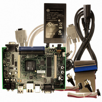
KIT DEVELOPMENT EP9315 ARM9
Manufacturer
Cirrus Logic Inc
Type
MCUr
Specifications of EDB9315A-Z
Contents
Development Board, Software, Schematics, Gerbers, Power Supply, Cable and Documentation
Silicon Manufacturer
Cirrus Logic
Core Architecture
ARM
Core Sub-architecture
ARM9
Features
Serial EEPROM Interface, 10/100 Mbps Ethernet, External Battery Backed RTC
Silicon Family Name
ARM
Silicon Core Number
EP9315
Rohs Compliant
Yes
Lead Free Status / RoHS Status
Lead free / RoHS Compliant
For Use With/related Products
EP9312, EP9315
Lead Free Status / RoHS Status
Lead free / RoHS Compliant, Lead free / RoHS Compliant
Other names
598-1144
EDB9315A
EDB9315A


EDB9315A
Technical Reference Manual
Page 5
This is the power section for the EP9315 device. The ADC and PLL supplies are filtered. There is no
reason to filter the 3.3 and the 1.8V power rails.
Page 6
The SDRAM interface is comprised of two 16-bit SDRAM devices to form a 32-bit SDRAM bus. The
SDRAM is connected to /SDCS0 and is located at physical memory address 0xC000_0000. Single 32-
bit SDRAM devices may be used as well.
The Flash interface is made from a single 16-bit device. It uses a "multi-cell" Flash device. The Flash
device is connected to /CS6 and is located at physical memory address 0x6000_0000. The reference
design uses only one Flash device. However, the EP9315 can be designed with a 32-bit Flash interface
as well. The Flash device installed is a 128 Mbit, 16 Mbyte, device.
The serial EEPROM is a 4 Mbit device and may be used for serial "SPI Boot" or for storing the Ethernet
MAC address. SPI Boot is not used as the default boot method but may be used by the developer if it fits
his/her application. Details about SPI Boot are in the EP9315 User's Guide. The serial EEPROM is
accessed only if the EGPIO7 line is configured to the proper level. The SPI™ frame signal and the
EGPIO7 "enable" signal are OR'ed to create the enable for the serial EEPROM device. EGPIO7 must be
low in order to communicate to the serial EEPROM. Other devices on the SPI bus must be enabled in a
similar manner but not enabled simultaneously.
Note: EGPIO7 should be pulled low instead of pulled high. If SPI Boot is desired, remove R201 and pull down
EGPIO7.
Page 7
The JTAG interface is connected to a 2x10 header, JP3. This connector is wired for the Multi-ICE
debugger.
There are 10 signals that determine how the EP9315 will boot and operate. They are all shown on this
page except for BOOT1. BOOT1 is connected to GND. BOOT1 is used for factory testing only. The other
nine signals are either pulled up or down external to the EP9315 device. The boot configuration shown
sets the EP9315 device to perform an Internal Async boot from a 16-bit-wide memory.
The “Serial Boot” pushbutton, S2, is used to configure the board to perform a serial boot. A serial boot is
used to program the Flash device with the Cirrus Logic download utility. Instead of using jumpers, a
pushbutton is used. Simply hold the pushbutton down while pressing and releasing the reset pushbutton,
S3. Continue to hold S2 until the red LED turns off. Once the red LED is off, release S2.
The ISL1208 is connected to the EP9315 to provided an external, battery backed RTC clock. This device
has 2 bytes of battery backed SRAM. The battery is a common lithium coin cell and easily removable if
desired.
Page 8
The Micrel KS8721Bl PHY is used to provide the 10/100 Mbit Ethernet interface. The PHY is attached to
the EP9315 device MII interface. The PHY also connects to RJ45 connector, J3. The Ethernet connector
has integrated magnetics and status LEDs. The Micrel PHY requires external power filtering of the 2.5V
supply it produces.
©
12
Copyright 2006 Cirrus Logic, Inc.
DS638DB3
Related parts for EDB9315A-Z
Image
Part Number
Description
Manufacturer
Datasheet
Request
R

Part Number:
Description:
Microprocessor Development Tool
Manufacturer:
Cirrus Logic Inc
Datasheet:

Part Number:
Description:
Development Kit
Manufacturer:
Cirrus Logic Inc
Datasheet:
Part Number:
Description:
Development Kit
Manufacturer:
Cirrus Logic Inc
Datasheet:


Part Number:
Description:
High-efficiency PFC + Fluorescent Lamp Driver Reference Design
Manufacturer:
Cirrus Logic Inc
Datasheet:
Part Number:
Description:
Development Kit
Manufacturer:
Cirrus Logic Inc
Datasheet:
Part Number:
Description:
Development Kit
Manufacturer:
Cirrus Logic Inc
Datasheet:

Part Number:
Description:
Development Kit
Manufacturer:
Cirrus Logic Inc
Datasheet:
Part Number:
Description:
Development Kit
Manufacturer:
Cirrus Logic Inc
Datasheet:
Part Number:
Description:
Development Kit
Manufacturer:
Cirrus Logic Inc
Datasheet:

Part Number:
Description:
EVALUATION BOARD FOR CS8427
Manufacturer:
Cirrus Logic Inc
Datasheet:

Part Number:
Description:
BOARD EVAL FOR CS8416 RCVR
Manufacturer:
Cirrus Logic Inc
Datasheet:

Part Number:
Description:
EVALUATION BOARD FOR CS8420
Manufacturer:
Cirrus Logic Inc
Datasheet:

Part Number:
Description:
KIT DEVELOPMENT EP9302 ARM9
Manufacturer:
Cirrus Logic Inc
Datasheet:

Part Number:
Description:
KIT DEVELOPMENT EP9307 ARM9
Manufacturer:
Cirrus Logic Inc
Datasheet: