101-0678 Rabbit Semiconductor, 101-0678 Datasheet - Page 25
101-0678
Manufacturer Part Number
101-0678
Description
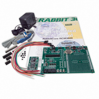
KIT DEV RABBITCORE/RCM3600
Manufacturer
Rabbit Semiconductor
Series
RabbitCore 3000r
Type
MPU Moduler
Datasheet
1.20-101-0673.pdf
(136 pages)
Specifications of 101-0678
Rohs Status
RoHS non-compliant
Contents
RabbitCore Module, Dev. Board, AC Adapter, Cable and Dynamic C® CD-Rom
Processor To Be Evaluated
RCM3600
For Use With/related Products
RCM3600
Lead Free Status / Rohs Status
Lead free / RoHS Compliant
Other names
316-1037


•
•
•
Before running the next two sample programs,
connect your PC serial COM port to header J2 on the Prototyping Board as follows.
• Tx to RxE
• Rx to TxE
• GND to GND
Then connect pins 1–3 and 2–4 on header JP2 on the Prototyping Board.
Now start Tera Term on your PC. Once Tera Term is running, configure the serial parame-
ters as follows:
• Baud rate 19200, 8 bits, no parity, and 1 stop bit.
• Enable the "Local Echo" option.
• Set the line feed options to Receive = CR and Transmit = CR + LF.
Now press
Please Send Data file" is being display in Tera Term display window before proceeding.
From within Tera Term, select
OPEN option within the dialog box. Once the data file has been downloaded, it will indi-
cate whether the calibration data were written successfully.
•
Getting Started
AD_SAMPLE.C
The program will continuously display the voltage (average of 10 samples) that is
present on the A/D channels.
Before running this program, make sure that pins 3–5 are connected on headers JP5,
JP6, and JP7 on the Prototyping Board. No pins are connected on header JP8.
ANAINCONFIG.C
ended analog input values for display as voltages. The sample program uses the func-
tion call
Before running this program, make sure that pins 3–5 are connected on headers JP5,
JP6, and JP7 on the Prototyping Board. No pins are connected on header JP8. Also con-
nect PE4 on header J3 on the Prototyping Board to the CNVRT terminal on header J8;
if you are using this sample program as a template for your own program, be aware that
PE4 is also used as the IrDA FIR_SEL pin.
THERMISTOR.C
temperature for display to the
thermistor is the one included in the Development Kit whose values for beta, series
resistance, and resistance at standard temperature are given in the part specification.
Before running this program, install the thermistor into the AIN7 and AGND holes at
location J7 on the Prototyping Board.
DNLOADCALIB.C
back to simulated EEPROM in flash with using a serial utility such as Tera Term.
F9
anaInConfig()
to compile and run this program. Verify that the message "Waiting,
—Demonstrates how to use a low-level driver on single-ended inputs.
—Demonstrates how to use analog input THERM_IN7 to calculate
—Demonstrates how to use the Register Mode method to read single-
—Demonstrates how to retrieve analog calibration data to rewrite it
and the ADS7870 CONVERT line to accomplish this task.
File > Send File > Path and filename
STDIO
window. This sample program assumes that the
DNLOADCALIB.C
or
UPLOADCALIB.C
, then select the
,
19
Related parts for 101-0678
Image
Part Number
Description
Manufacturer
Datasheet
Request
R

Part Number:
Description:
COMPUTER SNGLBD BL2101 A/D 0-10V
Manufacturer:
Rabbit Semiconductor
Part Number:
Description:
CARD D/A 0-10V SR9400 SMARTSTAR
Manufacturer:
Rabbit Semiconductor
Datasheet:
Part Number:
Description:
CARD A/D 0-10V SR9300 SMARTSTAR
Manufacturer:
Rabbit Semiconductor
Datasheet:

Part Number:
Description:
WiFi / 802.11 Modules & Development Tools WIRELESS CONTROL APP KIT
Manufacturer:
Rabbit Semiconductor

Part Number:
Description:
KIT DEV RABBITCORE RCM3750
Manufacturer:
Rabbit Semiconductor
Datasheet:
Part Number:
Description:
KIT DEV RABBIT 2000 INT'L
Manufacturer:
Rabbit Semiconductor
Datasheet:
Part Number:
Description:
KIT DEV RABBIT RCM2000 INT'L
Manufacturer:
Rabbit Semiconductor
Datasheet:

Part Number:
Description:
KIT DEVELOPMENT RCM3700 INT'L
Manufacturer:
Rabbit Semiconductor
Datasheet:

Part Number:
Description:
BL4S200 TOOL KIT
Manufacturer:
Rabbit Semiconductor
Datasheet:
Part Number:
Description:
MODULE RABBITCORE RCM3720
Manufacturer:
Rabbit Semiconductor
Datasheet:
Part Number:
Description:
MODULE RABBITCORE RCM3220
Manufacturer:
Rabbit Semiconductor
Datasheet:
Part Number:
Description:
MODULE RABBITCORE RCM3210
Manufacturer:
Rabbit Semiconductor
Datasheet:
Part Number:
Description:
COMPUTER SGL-BOARD OP6600 W/SRAM
Manufacturer:
Rabbit Semiconductor
Datasheet:
Part Number:
Description:
COMPUTER SGL-BD BL2000 SRAM/FLSH
Manufacturer:
Rabbit Semiconductor