DM180021 Microchip Technology, DM180021 Datasheet - Page 38
DM180021
Manufacturer Part Number
DM180021
Description
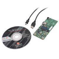
KIT STARTER MPLAB FOR PIC18F MCU
Manufacturer
Microchip Technology
Series
MPLAB®r
Type
MCUr
Specifications of DM180021
Contents
Board, Cable, CD
Processor To Be Evaluated
PIC18F46J50
Processor Series
PIC18F
Interface Type
SPI
Operating Supply Voltage
3.3 V
Silicon Manufacturer
Microchip
Core Architecture
PIC
Core Sub-architecture
PIC18
Silicon Core Number
PIC18F
Silicon Family Name
PIC18F4xxx
Kit Contents
Board
Lead Free Status / RoHS Status
Lead free / RoHS Compliant
For Use With/related Products
PIC18Fxxxx
Lead Free Status / Rohs Status
Lead free / RoHS Compliant
Available stocks
Company
Part Number
Manufacturer
Quantity
Price
Company:

Part Number:
DM180021
Manufacturer:
Microchip Technology
Quantity:
135
Company:
Part Number:
DM180021
Manufacturer:
MICROCHIP
Quantity:
12 000


MPLAB Starter Kit for PIC18F User’s Guide
B.2
DS51852A-page 34
PIC18F SOFT START CIRCUITRY
One strategy to meet the key USB current specifications is to include a software
controllable soft start mechanism. The starter kit implements the simple soft start circuit
shown in Figure B-1.
FIGURE B-1:
Transistor, Q1, a power MOSFET, blocks the current from the 3.3V power rail to the
non-microcontroller portions of the application circuit (e.g., SD card, OLED, etc). R21
ensures that on initial power-up, Q1 is blocking the current flow. R20 and C16 form an
RC filter on the digital output from the microcontroller (RC0 port). This RC filter creates
an analog voltage on the gate of Q1 from the PWM signal supplied by the micro-
controller. The values of C16 and R20 are chosen to produce a large RC time constant
compared to the PWM frequency, and such that, the current drawn from the pin is within
the port pin’s specification.
The PWM frequency is based on the RC network and is chosen to produce a fairly
constant voltage on the gate of Q1. The PWM duty cycle is determined by the gate
threshold of Q1. Once the frequency is selected, changing the PWM duty cycle will
result in a change of the gate voltage. The duty cycle is set so that the starting voltage
on the gate of Q1 is above the threshold voltage across all device variations, so that
the device is in an OFF state. The duty cycle is varied at a rate in which the gate voltage
on Q1 changes slowly enough to ensure that the transistor stays in its linear region dur-
ing the full charging of Q1’s output (Figure B-2). The result is that voltage is supplied to
the application at a slower rate, thus lowering the inrush current.
The duty cycle should stop sweeping at a point that is lower than any possible value for
Q1’s threshold voltage; this ensures that the entire linear region is used for as long as
possible. Once this point is reached, the software can disable the PWM and set the
output of RC0 low; this puts Q1 in Full Saturation mode.
Figure B-2 and Figure B-3 show how the change in gate voltage (yellow trace) relates
to the change in the circuit’s output (blue trace). Figure B-2 captures a close look at the
linear region, while Figure B-3 captures the entire PWM cycle from no output to full out-
put. Note that the gate voltage decreases slowly and constantly over the entire potential
threshold voltage range of Q1.
PIC18F STARTER KIT SOFT START CIRCUIT
APP_VDD
+3.3V
C16
0.1 μF
Q1
IRLML6402PBF
R21
100k
R20
1.5k
RC0
© 2009 Microchip Technology Inc.
Related parts for DM180021
Image
Part Number
Description
Manufacturer
Datasheet
Request
R

Part Number:
Description:
Manufacturer:
Microchip Technology Inc.
Datasheet:
Part Number:
Description:
Manufacturer:
Microchip Technology Inc.
Datasheet:
Part Number:
Description:
Manufacturer:
Microchip Technology Inc.
Datasheet:
Part Number:
Description:
Manufacturer:
Microchip Technology Inc.
Datasheet:
Part Number:
Description:
Manufacturer:
Microchip Technology Inc.
Datasheet:
Part Number:
Description:
Manufacturer:
Microchip Technology Inc.
Datasheet:
Part Number:
Description:
Manufacturer:
Microchip Technology Inc.
Datasheet:
Part Number:
Description:
Manufacturer:
Microchip Technology Inc.
Datasheet: