DM180021 Microchip Technology, DM180021 Datasheet - Page 16
DM180021
Manufacturer Part Number
DM180021
Description
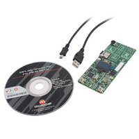
KIT STARTER MPLAB FOR PIC18F MCU
Manufacturer
Microchip Technology
Series
MPLAB®r
Type
MCUr
Specifications of DM180021
Contents
Board, Cable, CD
Processor To Be Evaluated
PIC18F46J50
Processor Series
PIC18F
Interface Type
SPI
Operating Supply Voltage
3.3 V
Silicon Manufacturer
Microchip
Core Architecture
PIC
Core Sub-architecture
PIC18
Silicon Core Number
PIC18F
Silicon Family Name
PIC18F4xxx
Kit Contents
Board
Lead Free Status / RoHS Status
Lead free / RoHS Compliant
For Use With/related Products
PIC18Fxxxx
Lead Free Status / Rohs Status
Lead free / RoHS Compliant
Available stocks
Company
Part Number
Manufacturer
Quantity
Price
Company:

Part Number:
DM180021
Manufacturer:
Microchip Technology
Quantity:
135
Company:
Part Number:
DM180021
Manufacturer:
MICROCHIP
Quantity:
12 000


MPLAB Starter Kit for PIC18F User’s Guide
2.3
DS51852A-page 12
USB HID JOYSTICK DEMO
This demo uses the starter kit as a USB joystick.
To test the joystick feature, open the Game Controller applet in the Control Panel. In
the following dialog, select “Joystick Demo” under “Installed Game Controllers”, then
click Properties. At the “Joystick Demo properties” dialog, select the Test tab to show
the interactive test display (Figure 2-4).
FIGURE 2-4:
The following controls are implemented in the Joystick Demo:
1. X-Axis/Y-Axis: The movement of the cursor around the white area is controlled
2. Z-Axis: The Z-axis is controlled using the scroll bar. Touch the bar and slide your
3. Z-Rotation: Rotation around the Z-axis is controlled with the potentiometer.
4. Buttons 1 and 2: Of the 13 buttons displayed, buttons 1 and 2 are controlled
using the on-board accelerometer. Like the Mouse Demo, acceleration on all
three axes is used to compute board tilt, which is then converted to movement
on the X and Y axis. While holding the starter kit board so that the USB connector
faces towards you, tilt the board to the right and left to change the X-axis position.
Tilt the board up and down to change the Y-axis position.
finger towards the bottom or top to change the Z-axis position.
Rotate the potentiometer to change the rotation.
using the L and R touch pads, respectively. Press and hold the pad to turn on
(light up) the corresponding joystick indicator.
JOYSTICK DEMO PROPERTIES DIALOG
© 2009 Microchip Technology Inc.
Related parts for DM180021
Image
Part Number
Description
Manufacturer
Datasheet
Request
R

Part Number:
Description:
Manufacturer:
Microchip Technology Inc.
Datasheet:
Part Number:
Description:
Manufacturer:
Microchip Technology Inc.
Datasheet:
Part Number:
Description:
Manufacturer:
Microchip Technology Inc.
Datasheet:
Part Number:
Description:
Manufacturer:
Microchip Technology Inc.
Datasheet:
Part Number:
Description:
Manufacturer:
Microchip Technology Inc.
Datasheet:
Part Number:
Description:
Manufacturer:
Microchip Technology Inc.
Datasheet:
Part Number:
Description:
Manufacturer:
Microchip Technology Inc.
Datasheet:
Part Number:
Description:
Manufacturer:
Microchip Technology Inc.
Datasheet: