XCARD XC-2 XMOS, XCARD XC-2 Datasheet
XCARD XC-2
Specifications of XCARD XC-2


Related parts for XCARD XC-2


XCARD XC-2 Summary of contents
Page 1
... XC-2 Hardware Manual 2009/07/09 Authors: XMOS Copyright © 2009, XMOS Ltd. All Rights Reserved (V 1.4) ERSION ...
Page 2
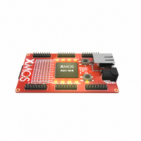
... XMOS 1 Introduction The XC Event-Driven Processor development card intended for design- ing Ethernet-based products such as audio/video bridging applications and in- dustrial control systems. It comprises a single XS1-G4 device, 10/100-BASE-T Ethernet PHY, 4Mbits SPI flash memory, 10 LEDs and two press-buttons. I/O ex- pansion areas are provided for connecting additional components, and an XSYS connector can be used to interface the card with a PC ...
Page 3
... XMOS 2 XS1-G4 Device [A] The XC-2 is based on a single XS1-G4 device in a 512BGA package. The XS1- G4 consists of four XCores, each comprising an event-driven multi-threaded pro- cessor with tightly integrated general purpose I/O pins and 64 KBytes of on-chip RAM. The pins are brought out of the package and connected to the card’s com- ...
Page 4
... XMOS 3 RJ45 Connector [B] and Ethernet PHY [J] The RJ45 connector is wired to the 10/100-BASE-T Ethernet PHY. The MII and MAC level protocols are implemented in software. 4 User LEDs [C] The XC-2 provides 10 user LEDs that can be driven by software. The layout of these LEDs is shown below. X3LEDB X3LEDA X2LEDA X2LEDB ...
Page 5
... XMOS 5 Push-Button Switches [D] The XC-2 provides two push-button switches whose states can be sampled at any time by software. The layout of these switches is shown below. The switches are connected to two pins, which are mapped to ports as described in the table below. Pin X0D14 P4C0 P8B0 PORT BUTTON A X0D16 P4D0 P8B2 PORT BUTTON B Each pin can be confi ...
Page 6
... XMOS 6 I/O Expansion Areas [E] The I/O pins of three of the processors are brought out to expansion areas on both sides of the card. These areas have 0.1” pitch through-plated holes and are suitable for use with IDC headers. To provide maximum flexibility, no headers are fitted, allowing the most suitable type to be selected depending on the design. ...
Page 7
... XMOS Pin Port XnD0 P1A0 XnD1 P1B0 XnD2 P4A0 P8A0 P16A0 XnD3 P4A1 P8A1 P16A1 XnD4 P4B0 P8A2 P16A2 XnD5 P4B1 P8A3 P16A3 XnD6 P4B2 P8A4 P16A4 XnD7 P4B3 P8A5 P16A5 XnD8 P4A2 P8A6 P16A6 XnD9 P4A3 P8A7 P16A7 XnD10 P1C0 ...
Page 8
... XMOS 6.1 XMOS Link Configuration Some of the I/O pins on the expansion header can be configured as XMOS Links. The mapping of XMOS Links to the headers is shown in the table below. Header 1/A XMOS Link 1 Pin 2 bit 5 bit X1D0 X1D1 XLA4 I X1D2 XLA3 I X1D3 ...
Page 9
... XMOS 7 Prototyping Area [F] The XC-2 provides a 0.1” pitch through-hole plated area for adding components to the card. The routing of I/O and power pins in the prototyping area is shown below. 5V The prototyping area provides a bank of 12 I/O pins, which are mapped to the ports as described in the table below. ...
Page 10
... SS_RESET PORT_UART_RX PORT_UART_TX The XMOS XTAG connector converts between XSYS and USB 2.0, allowing the XC connected to most PCs. On power on, the XS1-G4 boots from the on-board flash memory. The XS1-G4 can then be put into JTAG mode by the PC, which then boots another program. ...
Page 11
... XMOS If a UART is required, it can be implemented in software by sampling and driving these ports at the required rate. The XTAG performs a UART-to-USB conversion on these pins, presenting a virtual COM port to the PC that can be interfaced via a terminal emulator. 10 SPI Flash Memory [I] The XC-2 provides 4Mbit of Serial Peripheral Interface (SPI) flash memory, which is interfaced by the four 1-bit connections described in the table below ...
Page 12
... XMOS 13 Dimensions The XC-2 dimensions are 86 x 54mm. The mounting holes are 3mm in diameter. XC (1.4) ARDWARE ANUAL 11/16 2009/07/09 ...
Page 13
... ARDWARE ANUAL Processor 1 A PORT_LED_1_0/1 I/O HEADER 1A I/O HEADER 1B System Services PORT_UART RX PORT_UART TX XS1-G4 RESET RST PGOOD 1V CLOCK 25MHz XTO 3V3 I/O HEADER 3A I/O HEADER 3B Processor 3 PORT_LED_3_0/1 A 12/16 B XMOS LINK SS_TDI SS_TDO SS_TMS SS_TCK SS_TRST SS_DEBUG SS_RESET 5V SKT PSU B 2009/07/09 ...
Page 14
... XnD1 P1B0 PORT SPI SS XnD2 P4A0 P8A0 P16A0 XnD3 P4A1 P8A1 P16A1 XnD4 P4B0 P8A2 P16A2 Host XnD5 P4B1 P8A3 P16A3 XMOS XnD6 P4B2 P8A4 P16A4 LINK XnD7 P4B3 P8A5 P16A5 XnD8 P4A2 P8A6 P16A6 XnD9 P4A3 P8A7 P16A7 XnD10 P1C0 ...
Page 15
... XMOS 15 XC-2 XN File The XCore ports linked to the hardware features on the XC-2 are mapped to generic port identifiers as part of a platform specific XN file, which simplifies the process of porting a project between platforms. The following table lists the defined identifiers for processors and 3: ...
Page 16
... References [1] Douglas Watt. XC-2 Ethernet Kit Tutorial. Website, 2009. xmos.com/published/xc2tut [2] Douglas Watt. Programming XC on XCore XS1 Devices. Website, 2009. http://www.xmos.com/published/xcxs1 [3] David May and Henk Muller. XCore XS1 Architecture Tutorial. Website, 2009. http://www.xmos.com/published/xs1tut XC (1.4) ARDWARE ANUAL http://www ...
Page 17
... XMOS Ltd is the owner or licensee of this design, code, or Information (collec- tively, the “Information”) and is providing it to you “AS IS” with no warranty of any kind, express or implied and shall have no liability in relation to its use. XMOS Ltd makes no representation that the Information, or any particular implementa- tion thereof will be free from any claims of infringement and again, shall have no liability in relation to any such claims ...