C8051F320DK Silicon Laboratories Inc, C8051F320DK Datasheet - Page 165
C8051F320DK
Manufacturer Part Number
C8051F320DK
Description
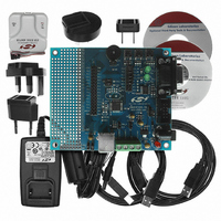
DEV KIT FOR C8051F320/F321
Manufacturer
Silicon Laboratories Inc
Type
MCUr
Specifications of C8051F320DK
Contents
Evaluation Board, Power Supply, USB Cables, Adapter and Documentation
Processor To Be Evaluated
C8051F320/F321
Interface Type
USB
Silicon Manufacturer
Silicon Labs
Core Architecture
8051
Silicon Core Number
C8051F320
Silicon Family Name
C8051F32x
Lead Free Status / RoHS Status
Contains lead / RoHS non-compliant
For Use With/related Products
Silicon Laboratories C8051F320, C8051F321
Lead Free Status / Rohs Status
Lead free / RoHS Compliant
Other names
336-1260
Available stocks
Company
Part Number
Manufacturer
Quantity
Price
Company:

Part Number:
C8051F320DK
Manufacturer:
SiliconL
Quantity:
4


C8051F320/1
A Bulk or Interrupt pipe can be shut down (or Halted) by writing ‘1’ to the SDSTL bit (EOUTCSRL.5). While
SDSTL = ‘1’, hardware will respond to all OUT requests with a STALL condition. Each time hardware gen-
erates a STALL condition, an interrupt will be generated and the STSTL bit (EOUTCSRL.6) set to ‘1’. The
STSTL bit must be reset to ‘0’ by firmware.
Hardware will automatically set OPRDY when a packet is ready in the OUT FIFO. Note that if double buff-
ering is enabled for the target endpoint, it is possible for two packets to be ready in the OUT FIFO at a time.
In this case, hardware will set OPRDY to ‘1’ immediately after firmware unloads the first packet and resets
OPRDY to ‘0’. A second interrupt will be generated in this case.
15.13.2.Endpoints1-3 OUT Isochronous Mode
When the ISO bit (EOUTCSRH.6) is set to ‘1’, the target endpoint operates in Isochronous (ISO) mode.
Once an endpoint has been configured for ISO OUT mode, the host will send exactly one data per USB
frame; the location of the data packet within each frame may vary, however. Because of this, it is recom-
mended that double buffering be enabled for ISO OUT endpoints.
Each time a data packet is received, hardware will load the received data packet into the endpoint FIFO,
set the OPRDY bit (EOUTCSRL.0) to ‘1’, and generate an interrupt (if enabled). Firmware would typically
use this interrupt to unload the data packet from the endpoint FIFO and reset the OPRDY bit to ‘0’.
If a data packet is received when there is no room in the endpoint FIFO, an interrupt will be generated and
the OVRUN bit (EOUTCSRL.2) set to ‘1’. If USB0 receives an ISO data packet with a CRC error, the data
packet will be loaded into the endpoint FIFO, OPRDY will be set to ‘1’, an interrupt (if enabled) will be gen-
erated, and the DATAERR bit (EOUTCSRL.3) will be set to ‘1’. Software should check the DATAERR bit
each time a data packet is unloaded from an ISO OUT endpoint FIFO.
Rev. 1.4
165
Related parts for C8051F320DK
Image
Part Number
Description
Manufacturer
Datasheet
Request
R

Part Number:
Description:
SMD/C°/SINGLE-ENDED OUTPUT SILICON OSCILLATOR
Manufacturer:
Silicon Laboratories Inc
Part Number:
Description:
Manufacturer:
Silicon Laboratories Inc
Datasheet:
Part Number:
Description:
N/A N/A/SI4010 AES KEYFOB DEMO WITH LCD RX
Manufacturer:
Silicon Laboratories Inc
Datasheet:
Part Number:
Description:
N/A N/A/SI4010 SIMPLIFIED KEY FOB DEMO WITH LED RX
Manufacturer:
Silicon Laboratories Inc
Datasheet:
Part Number:
Description:
N/A/-40 TO 85 OC/EZLINK MODULE; F930/4432 HIGH BAND (REV E/B1)
Manufacturer:
Silicon Laboratories Inc
Part Number:
Description:
EZLink Module; F930/4432 Low Band (rev e/B1)
Manufacturer:
Silicon Laboratories Inc
Part Number:
Description:
I°/4460 10 DBM RADIO TEST CARD 434 MHZ
Manufacturer:
Silicon Laboratories Inc
Part Number:
Description:
I°/4461 14 DBM RADIO TEST CARD 868 MHZ
Manufacturer:
Silicon Laboratories Inc
Part Number:
Description:
I°/4463 20 DBM RFSWITCH RADIO TEST CARD 460 MHZ
Manufacturer:
Silicon Laboratories Inc
Part Number:
Description:
I°/4463 20 DBM RADIO TEST CARD 868 MHZ
Manufacturer:
Silicon Laboratories Inc
Part Number:
Description:
I°/4463 27 DBM RADIO TEST CARD 868 MHZ
Manufacturer:
Silicon Laboratories Inc
Part Number:
Description:
I°/4463 SKYWORKS 30 DBM RADIO TEST CARD 915 MHZ
Manufacturer:
Silicon Laboratories Inc
Part Number:
Description:
N/A N/A/-40 TO 85 OC/4463 RFMD 30 DBM RADIO TEST CARD 915 MHZ
Manufacturer:
Silicon Laboratories Inc
Part Number:
Description:
I°/4463 20 DBM RADIO TEST CARD 169 MHZ
Manufacturer:
Silicon Laboratories Inc