C8051F320DK Silicon Laboratories Inc, C8051F320DK Datasheet - Page 157
C8051F320DK
Manufacturer Part Number
C8051F320DK
Description
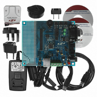
DEV KIT FOR C8051F320/F321
Manufacturer
Silicon Laboratories Inc
Type
MCUr
Specifications of C8051F320DK
Contents
Evaluation Board, Power Supply, USB Cables, Adapter and Documentation
Processor To Be Evaluated
C8051F320/F321
Interface Type
USB
Silicon Manufacturer
Silicon Labs
Core Architecture
8051
Silicon Core Number
C8051F320
Silicon Family Name
C8051F32x
Lead Free Status / RoHS Status
Contains lead / RoHS non-compliant
For Use With/related Products
Silicon Laboratories C8051F320, C8051F321
Lead Free Status / Rohs Status
Lead free / RoHS Compliant
Other names
336-1260
Available stocks
Company
Part Number
Manufacturer
Quantity
Price
Company:

Part Number:
C8051F320DK
Manufacturer:
SiliconL
Quantity:
4


15.9. The Serial Interface Engine
The Serial Interface Engine (SIE) performs all low level USB protocol tasks, interrupting the processor
when data has successfully been transmitted or received. When receiving data, the SIE will interrupt the
processor when a complete data packet has been received; appropriate handshaking signals are automat-
ically generated by the SIE. When transmitting data, the SIE will interrupt the processor when a complete
data packet has been transmitted and the appropriate handshake signal has been received.
The SIE will not interrupt the processor when corrupted/erroneous packets are received.
15.10. Endpoint0
Endpoint0 is managed through the USB register E0CSR (Figure 15.17). The INDEX register must be
loaded with 0x00 to access the E0CSR register.
An Endpoint0 interrupt is generated when:
Bits7–4: Unused. Read = 0000b; Write = don’t care.
Bit3:
Bit2:
Bit1:
Bit0:
R/W
Bit7
-
USB Register Definition 15.16. CMIE: USB0 Common Interrupt Enable
1. A data packet (OUT or SETUP) has been received and loaded into the Endpoint0 FIFO. The
2. An IN data packet has successfully been unloaded from the Endpoint0 FIFO and transmitted
3. An IN transaction is completed (this interrupt generated during the status stage of the transac-
4. Hardware sets the STSTL bit (E0CSR.2) after a control transaction ended due to a protocol
5. Hardware sets the SUEND bit (E0CSR.4) because a control transfer ended before firmware
OPRDY bit (E0CSR.0) is set to ‘1’ by hardware.
to the host; INPRDY is reset to ‘0’ by hardware.
tion).
violation.
sets the DATAEND bit (E0CSR.3).
SOFE: Start of Frame Interrupt Enable
0: SOF interrupt disabled.
1: SOF interrupt enabled.
RSTINTE: Reset Interrupt Enable
0: Reset interrupt disabled.
1: Reset interrupt enabled.
RSUINTE: Resume Interrupt Enable
0: Resume interrupt disabled.
1: Resume interrupt enabled.
SUSINTE: Suspend Interrupt Enable
0: Suspend interrupt disabled.
1: Suspend interrupt enabled.
R/W
Bit6
-
R/W
Bit5
-
R/W
Bit4
-
Rev. 1.4
SOFE
R/W
Bit3
RSTINTE RSUINTE SUSINTE 00000110
R/W
Bit2
R/W
Bit1
C8051F320/1
R/W
Bit0
USB Address:
Reset Value
0x0B
157
Related parts for C8051F320DK
Image
Part Number
Description
Manufacturer
Datasheet
Request
R

Part Number:
Description:
SMD/C°/SINGLE-ENDED OUTPUT SILICON OSCILLATOR
Manufacturer:
Silicon Laboratories Inc
Part Number:
Description:
Manufacturer:
Silicon Laboratories Inc
Datasheet:
Part Number:
Description:
N/A N/A/SI4010 AES KEYFOB DEMO WITH LCD RX
Manufacturer:
Silicon Laboratories Inc
Datasheet:
Part Number:
Description:
N/A N/A/SI4010 SIMPLIFIED KEY FOB DEMO WITH LED RX
Manufacturer:
Silicon Laboratories Inc
Datasheet:
Part Number:
Description:
N/A/-40 TO 85 OC/EZLINK MODULE; F930/4432 HIGH BAND (REV E/B1)
Manufacturer:
Silicon Laboratories Inc
Part Number:
Description:
EZLink Module; F930/4432 Low Band (rev e/B1)
Manufacturer:
Silicon Laboratories Inc
Part Number:
Description:
I°/4460 10 DBM RADIO TEST CARD 434 MHZ
Manufacturer:
Silicon Laboratories Inc
Part Number:
Description:
I°/4461 14 DBM RADIO TEST CARD 868 MHZ
Manufacturer:
Silicon Laboratories Inc
Part Number:
Description:
I°/4463 20 DBM RFSWITCH RADIO TEST CARD 460 MHZ
Manufacturer:
Silicon Laboratories Inc
Part Number:
Description:
I°/4463 20 DBM RADIO TEST CARD 868 MHZ
Manufacturer:
Silicon Laboratories Inc
Part Number:
Description:
I°/4463 27 DBM RADIO TEST CARD 868 MHZ
Manufacturer:
Silicon Laboratories Inc
Part Number:
Description:
I°/4463 SKYWORKS 30 DBM RADIO TEST CARD 915 MHZ
Manufacturer:
Silicon Laboratories Inc
Part Number:
Description:
N/A N/A/-40 TO 85 OC/4463 RFMD 30 DBM RADIO TEST CARD 915 MHZ
Manufacturer:
Silicon Laboratories Inc
Part Number:
Description:
I°/4463 20 DBM RADIO TEST CARD 169 MHZ
Manufacturer:
Silicon Laboratories Inc