TWR-MCF51CN-KIT Freescale Semiconductor, TWR-MCF51CN-KIT Datasheet - Page 15
TWR-MCF51CN-KIT
Manufacturer Part Number
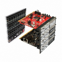
TWR-MCF51CN-KIT
Description
KIT TOWER BOARD/SERIAL/ELEVATOR
Manufacturer
Freescale Semiconductor
Series
ColdFire®, Flexis™r
Type
MCUr
Datasheets
1.TWR-ELEV.pdf
(48 pages)
2.TWR-ELEV.pdf
(4 pages)
3.TWR-ELEV.pdf
(4 pages)
4.TWR-MCF51CN-KIT.pdf
(4 pages)
Specifications of TWR-MCF51CN-KIT
Contents
4 Boards, Cable, DVD
Processor To Be Evaluated
MCF51CN128
Data Bus Width
8 bit, 16 bit, 32 bit
Interface Type
RS-232, RS-485, Ethernet, USB, CAN
Silicon Manufacturer
Freescale
Core Architecture
Coldfire
Core Sub-architecture
Coldfire V1
Silicon Core Number
MCF51
Silicon Family Name
MCF51CN
Kit Contents
Board
Rohs Compliant
Yes
For Use With/related Products
Freescale Tower System, MCF51CN128
For Use With
TWR-ELEV - TOWER ELEVATOR BOARDS HARDWARE
Lead Free Status / RoHS Status
Lead free / RoHS Compliant


Num C
3.6
This section includes information about power supply requirements and I/O pin characteristics.
Freescale Semiconductor
10
11
12
13
14
15
16
1
2
3
4
5
6
7
8
9
— Operating Voltage
C
P
T
C
D
C
P
T
C
D
P Input high
C
P Input low voltage
C
C Input hysteresis
P
P
P
D
C Input Capacitance, all pins
C POR re-arm voltage
D POR re-arm time
P
Output high
voltage
Output high
current
Output low
voltage
Output low
current
voltage
Input leakage
current
Hi-Z (off-state)
leakage current
Pull resistors
DC injection
current
Low-voltage detection threshold —
high range
DC Characteristics
4, 5, 6
8
Characteristic
2
Total MCU limit, includes
sum of all stressed pins
7
all digital inputs, when
MCF51CN128 ColdFire Microcontroller Data Sheet, Rev. 4
Max total I
Max total I
high-drive strength
high-drive strength
low-drive strength
low-drive strength
all input only pins
all digital inputs
all digital inputs
all digital inputs
all input/output
Single pin limit
All I/O pins,
All I/O pins,
All I/O pins,
All I/O pins,
OH
(Per pin)
OL
(per pin)
enabled
Table 8. DC Characteristics
for all
for all
ports
ports
Symbol
V
V
t
I
V
|I
V
V
I
LVDH
V
POR
OHT
V
|I
C
OLT
R
I
POR
—
OZ|
OH
hys
IC
OL
In|
IH
IL
In
P
9
2.7 V, I
V
1.8 V, I
2.3 V, I
2.7 V, I
1.8V, I
1.8 V, I
2.3 V, I
1.8 V, I
IN
V
V
In
In
< V
V
V
V
V
V
Condition
V
= V
= V
DD
DD
DD
DD
Load
DD
DD
Load
Load
Load
Load
SS
Load
Load
Load
DD
DD
—
—
—
> 2.7 V
> 1.8 V
> 2.7 V
—
—
>1.8 V
, V
falling
rising
= –10 mA V
= –3 mA
= –2 mA
= –6 mA
= 10 mA
or V
or V
IN
= 2 mA
= 6 mA
= 3 mA
> V
SS
SS
DD
0.70 x V
0.85 x V
0.06 x V
V
V
V
DD
DD
DD
DD
17.5
–0.2
2.15
2.24
1.8
Min
0.9
–5
10
—
—
—
—
—
—
—
—
—
—
—
– 0.5
– 0.5
– 0.5
– 0.5
3
DD
DD
DD
Electrical Characteristics
Typ
2.32
2.39
0.1
0.1
1.4
—
—
—
—
—
—
—
—
—
—
—
—
—
—
—
—
—
—
—
—
—
1
0.35 x V
0.30 x V
Max
52.5
1.79
2.45
2.49
100
100
3.6
0.5
0.5
0.5
0.5
0.2
—
—
—
—
—
—
—
—
1
1
5
8
DD
DD
Unit
mA
mA
mV
mA
mA
μA
μA
kΩ
pF
μs
V
V
V
V
V
V
15
Related parts for TWR-MCF51CN-KIT
Image
Part Number
Description
Manufacturer
Datasheet
Request
R

Part Number:
Description:
LCD MODULE FOR TWR SYSTEM
Manufacturer:
Freescale Semiconductor
Datasheet:

Part Number:
Description:
TOWER ELEVATOR BOARDS HARDWARE
Manufacturer:
Freescale Semiconductor
Datasheet:

Part Number:
Description:
TOWER SERIAL I/O HARDWARE
Manufacturer:
Freescale Semiconductor
Datasheet:

Part Number:
Description:
MEMORY MODULE FOR TWR SYSTEM
Manufacturer:
Freescale Semiconductor
Datasheet:

Part Number:
Description:
MCU, MPU & DSP Development Tools TOWER CD MCF51AG128 KIT
Manufacturer:
Freescale Semiconductor

Part Number:
Description:
TOWER SYSTEM SENSOR PAK
Manufacturer:
Freescale Semiconductor
Datasheet:

Part Number:
Description:
KIT TOWER BOARD
Manufacturer:
Freescale Semiconductor
Datasheet:

Part Number:
Description:
TOWER SYSTEM BOARD MC9S08MM128
Manufacturer:
Freescale Semiconductor
Datasheet:

Part Number:
Description:
TOWER SYSTEM BOARD MCF51MM
Manufacturer:
Freescale Semiconductor
Datasheet:

Part Number:
Description:
MCU, MPU & DSP Development Tools For 9S08MM128 USB CAN
Manufacturer:
Freescale Semiconductor
Datasheet:
Part Number:
Description:
LCD MODULE FOR TWR SYSTEM
Manufacturer:
Freescale Semiconductor
Datasheet:

Part Number:
Description:
K53N512CMD100 TWR Module
Manufacturer:
Freescale Semiconductor
Datasheet:
Part Number:
Description:
TWR-K53N512 Dev Kit
Manufacturer:
Freescale Semiconductor
Datasheet:
Part Number:
Description:
TOWER ELEVATOR BOARDS HARDWARE
Manufacturer:
Freescale Semiconductor
Datasheet:
Part Number:
Description:
TOWER SERIAL I/O HARDWARE
Manufacturer:
Freescale Semiconductor
Datasheet: