MCF51CN128—Lab Tutorials 1 & 2
Security System,
Freescale MQX™ RTOS
for MCF51CN128
Introduction
This lab will guide you through the general
use of the Freescale MQX™ operating
system under the CodeWarrior™ integrated
development environment and will
familiarize you with the general compile
and download process. This lab will
simulate an Ethernet-enabled home security
system that is accessed over telnet.
Figure: Software Flow Chart
Demonstrates
• MQX project in CodeWarrior IDE
• Project build, download and run in
• Accelerometer
• MQX shell
• MQX GPIO driver (push button and LEDs)
• MQX RTCS TCP/IP network stack
• Telnet server functionality
Step by Step Instructions
1. Install CodeWarrior for Microcontrollers 6.2 (30
2. Press the card edge connector of the MCU
Start telnet server and
Initialize IO, ADC and
Lab Tutorials for TWR-MCF51CN-KIT
program parameters
listen for connection
bringup networking
LAB
Start RTCS and
CodeWarrior IDE
day evaluation version available, Basic or higher
required for MQX Lab tutorials) then install
CodeWarrior 6.2.2 patch. Then open CodeWarrior.
module into a slot on the Elevator—take
care to match the primary connector card
edges and plug them into a Functional
Elevator. Do the same for the serial module.
1
Main Task
“Main” task
Start IO task
Autostart
ADC inputs
Poll IO and
IO Task
3. Make the following connections from the
4. The first time you connect the USB debugger
5. If you are running the board for the very
6. If you did not install the MQX project in
7. Open the lab project by selecting the File
8. In the project pane, select the “SecTelnet -
Figure 2: Project Loaded in the CodeWarrior IDE
A module may be placed into any slot on the
Elevator, but it is recommended to put the
MCU module on the top for easier access to
the switches and LEDs.
Then press the Dummy Elevator onto the
card edges labeled secondary.
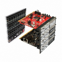
MCF51CN128 Tower System to the computer.
See Figure 1 on reverse side.
a. USB cable between the OSBDM debugger
(J14 on the TWR-MCF51CN module) and
b. Ethernet cable between the Ethernet port
on the TWR-SER module and an Ethernet
cable to your PC, Windows will install a driver
for the debugger. Follow the prompts to
automatically detect and install the driver.
first time, the telnet demo has already been
loaded on the board. Skip to Step 9 to setup
the network, and then skip to Step 16 to
run the demo. If you would like to re-flash
the board with the original demo code, then
continue onto the next step.
the default C:\Program Files\Freescale\
Freescale MQX 3.2\ directory during
installation, you must first recompile the
MQX libraries. See the release notes for
more information.
> Open menu, and opening: C:\Program
Files\Freescale\Freescale MQX 3.2\demo\
security_telnet\codewarrior\sectelnet_
twrmcf51cn.mcp
OSBDM Debug Int Flash” build target.
See Figure 2.
a USB port on PC
port on PC
9. The default IP address of the board is
Note: The PC may take a few minutes to default to the
auto IP address and make the connection. If you have
trouble connecting, you may configure the IP address
of the computer manually. Select Start > Control Panel
> Network Connections > Local Area Connection.
Open up the TCP/IP properties, Note your original
TCP/IP settings, and then set your IP address to
169.254.3.4 and your subnet mask to 255.255.0.0.
10. Open the Security.h file in the CodeWarrior
11. If you would like to change the default IP
Figure 3: MQX Source
12. Compile the project by pressing the F7 key or
13. Now start debugger by clicking the Debug
14. The V1 ColdFire debugger will appear with a
Figure 4: Re-Flashing the chip
15. After the code has been flashed to the board,
169.254.3.3. Typically, when you connect
your computer directly to the board,
the computer will default to an auto IP
address on the same subnet as the board
(169.254.x.x), therefore requiring no setup.
You may see a message from Windows
saying “Limited Connectivity” when doing
this, but that is expected.
window. Double-click the file item located
in the “Source” group in the CodeWarrior
project tree. See Figure 2.
address of the board, locate the line of code
starting with #define ENET_IPADDR and
specify your target IP address and IP mask
address by using the IPADDR macro. The
default IP address is 169.254.3.3 and subnet
mask is 255.255.0.0
by clicking the Make icon on the project pane
toolbar. This icon is identified in Figure 2.
icon. This icon is identified in Figure 2.
dialog box asking if you would like to erase
the flash and load it with the new software.
Select OK.
you will see the MQX entry-point function in
Figure 5: Debugger
16. Open a Command Prompt on the PC
17. At the prompt invoke a telnet session to the
Figure 6: Connect via telnet
18. Type help to see the list of available
Figure 7: Telnet commands
19. A simple Security system has been
20. The LEDs on the MCU board represent the
the code window. Hit the “Start” button
as seen in Figure 5.
(Start > Programs > Accessories >
Command Prompt)
board by typing telnet 169.254.3.3. You will
be connected to the Tower board via telnet.
commands.
implemented as the example application
to demonstrate the features of the MQX RTOS.
It detects button presses and movement of the
tower system, keeps a log of the events and
provides a user interface over telnet.
current state of the system.
• When the tower system is held flat, LED1,
LED2 and LED3 are controlled by the
• When the tower system is tilted, LED1,
LED2, and LED3 represent how far the
commands ledon and ledoff (ie ledon 2).
board is tilted in the Y-axis direction.
(sheet 1 of 2)
Figure 8: LEDs
21. Use the status command to see the current
Figure 9: Status Command
22. Hold SW2 down, representing the door, with
Figure 10: Display Log
23. Type displaylog to see the last 10 events
Figure 11: Display Log
24. Shake the Tower vigorously for a few
Figure 12: Display log
25. Use the ledon or ledoff commands to
Figure 13: LED Commands
• LED4 represents the Door (SW2) or
Window (SW3) status as OPEN or CLOSED
status of the board. It will display the current
state of the switches, potentiometer and
accelerometers, as well as the elapsed time
since bootup.
one hand, while typing status with the other
and hit the Enter key. You will see that the
door is Open.
that the tower system has detected. Clearlog
will clear the history.
seconds. Now type displaylog again.
control the LED GPIO.
Movement
Button Press
Web Security System,
Freescale MQX RTOS
for MCF51CN128
Introduction
This lab uses dynamic Web pages served
by the TWR-MCF51CN-KIT to serve as
a graphical user interface to the Security
application.
Figure: Software Flow Chart
Demonstrates
• MQX RTCS TCP/IP network stack
• HTTP Server functionality
Step by Step Instructions
1. Follow steps 1 through 4 in Lab 1 to setup
2. Open the Web Server Lab Project by
3. In the project pane, select “SecWebserver -
Initialize IO, ADC and
Start Web server and
program parameters
listen for connection
bringup networking
LAB
Start RTCS and
the Tower System.
selecting the File > Open menu, and opening:
C:\Program Files\Freescale\Freescale MQX
3.2\demo\security_webserver\codewarrior\
secwebserver_twrmcf51cn.mcp
OSBDM Debug Int. Flash” build target.
See Figure 1.
2
Main Task
“Main” task
Start IO task
Autostart
continued on reverse side...
TOWER SYSTEM
ADC inputs
Poll IO and
IO Task