Z8F04A08100KIT Zilog, Z8F04A08100KIT Datasheet - Page 3
Z8F04A08100KIT
Manufacturer Part Number
Z8F04A08100KIT
Description
KIT DEV Z8 ENCORE XP 8-PIN
Manufacturer
Zilog
Series
Z8 Encore! XP®r
Type
MCUr
Datasheets
1.Z8F04A08100KIT.pdf
(24 pages)
2.Z8F04A08100KIT.pdf
(2 pages)
3.Z8F04A08100KIT.pdf
(9 pages)
Specifications of Z8F04A08100KIT
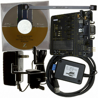
Contents
Hardware, Software and Documentation
For Use With/related Products
Z8 Encore! XP 8-pin
For Use With
269-4661 - KIT ACC ETHERNET SMART CABLE
Lead Free Status / RoHS Status
Contains lead / RoHS non-compliant
Other names
269-3638


3. Connect the serial port of the PC to the Z8 Encore! Smart Cable DB-9 female connec-
4. Connect the Z8 Encore! Smart Cable to development board pin header P2.
5. Connect the power supply to the development board at J1, then to an electrical outlet
Connecting the Power Supply
The universal power supply kit features four different plug adapters in one box and the
power supply itself in another. The power supply ships with a slide-out plate that must be
removed to insert the location-specific plug adapter.
1. Remove the slide-out plate.
2. Select the AC plug adapter appropriate for your locale and insert it into the slot that
3. Slide the new plug adapter into the slot until it snaps into place.
4. Plug the power supply into an electrical outlet.
QS004303-0205
Note:
this kit, refer to the Z8F04A08100KIT Z8 Encore! XP™ 4K Series User Manual,
UM0187.
tor.
(Figure 1 on page 4).
remains after removing the slide-out plate.
Caution:
Steps 3 and 4 below refer to installing the serial Z8 Encore! Smart Cable. For
instructions on installing the Z8 Encore! USB Smart Cable, refer to the USB
Smart Cable User Manual, UM0181, on the CD-ROM included with the
development kit.
Do not connect the power supply to the development board before con-
necting a Z8 Encore! Smart Cable to both the host PC and development
board.
Z8 Encore! XP
Setting up the Development Board
®
Development Kits
Quick Start Guide
Page 3
Related parts for Z8F04A08100KIT
Image
Part Number
Description
Manufacturer
Datasheet
Request
R

Part Number:
Description:
Communication Controllers, ZILOG INTELLIGENT PERIPHERAL CONTROLLER (ZIP)
Manufacturer:
Zilog, Inc.
Datasheet:

Part Number:
Description:
KIT DEV FOR Z8 ENCORE 16K TO 64K
Manufacturer:
Zilog
Datasheet:

Part Number:
Description:
KIT DEV Z8 ENCORE XP 28-PIN
Manufacturer:
Zilog
Datasheet:

Part Number:
Description:
DEV KIT FOR Z8 ENCORE 8K/4K
Manufacturer:
Zilog
Datasheet:

Part Number:
Description:
KIT DEV Z8 ENCORE XP 28-PIN
Manufacturer:
Zilog
Datasheet:

Part Number:
Description:
DEV KIT FOR Z8 ENCORE 4K TO 8K
Manufacturer:
Zilog
Datasheet:
Part Number:
Description:
CMOS Z8 microcontroller. ROM 16 Kbytes, RAM 256 bytes, speed 16 MHz, 32 lines I/O, 3.0V to 5.5V
Manufacturer:
Zilog, Inc.
Datasheet:
Part Number:
Description:
Low-cost microcontroller. 512 bytes ROM, 61 bytes RAM, 8 MHz
Manufacturer:
Zilog, Inc.
Datasheet:
Part Number:
Description:
Z8 4K OTP Microcontroller
Manufacturer:
Zilog, Inc.
Datasheet:
Part Number:
Description:
CMOS SUPER8 ROMLESS MCU
Manufacturer:
Zilog, Inc.
Datasheet:
Part Number:
Description:
SL1866 CMOSZ8 OTP Microcontroller
Manufacturer:
Zilog, Inc.
Datasheet:
Part Number:
Description:
SL1866 CMOSZ8 OTP Microcontroller
Manufacturer:
Zilog, Inc.
Datasheet:
Part Number:
Description:
OTP (KB) = 1, RAM = 125, Speed = 12, I/O = 14, 8-bit Timers = 2, Comm Interfaces Other Features = Por, LV Protect, Voltage = 4.5-5.5V
Manufacturer:
Zilog, Inc.
Datasheet:
Part Number:
Description:
Manufacturer:
Zilog, Inc.
Datasheet: