Z8F04A08100KIT Zilog, Z8F04A08100KIT Datasheet
Z8F04A08100KIT
Specifications of Z8F04A08100KIT


Related parts for Z8F04A08100KIT


Z8F04A08100KIT Summary of contents
Page 1
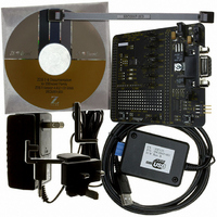
... Series 8-Pin Development Board ® – Z8 Encore! XP F08xA Series Development Board • Smart Cable for Encore! • (Z8F04A08100KIT development kits only) USB Smart Cable for Encore! Development Board and driver CD-ROM • Universal 5V power supply Software (on CD-ROM) ® • ZDS II–Z8 Encore! IDE with ANSI C-Compiler • ...
Page 2
... Setting up the Development Board The PC communicates with the Z8 Encore! development board using the serial port of the PC or, in the case of the Z8F04A08100KIT kit, the USB port of the PC. The Z8 Encore! serial Smart Cable and USB Smart Cable convert the RS-232 signals into the 3.3V bidi- rectional open-drain signal needed to communicate with the on-chip debugger ...
Page 3
... Z8F04A08100KIT Z8 Encore! XP™ 4K Series User Manual, UM0187. Steps 3 and 4 below refer to installing the serial Z8 Encore! Smart Cable. For Note: instructions on installing the Z8 Encore! USB Smart Cable, refer to the USB Smart Cable User Manual, UM0181, on the CD-ROM included with the development kit ...
Page 4
Z8 Encore! XP Development Kits Quick Start Guide Page 4 Serial Serial Port Smart Cable Development Board P2 Figure 1. Development Board External Connections (Serial Z8 Encore! Smart Cable shown) For convenience, you can leave the adapter slot cover ...
Page 5
... Next Unless you select a different location, the program is located in the → Programs ZiLOG ZDS II Z8 Encore! <version> ZDS II Z8 Encore! <version> 7. After selecting , the Next tions on the screen to complete the software registration. 8. When the installation is complete, a screen appears reminding you to register the development kit online ...
Page 6
... Z8 Encore! XP Development Kits Quick Start Guide Page 6 5. Browse to the Samples c:\Program Files\ZiLOG\ZDSII_Z8Encore_<version>\Samples the folder, select the Samples access the ledBlink.zdsproj Note: The sample used in the following steps is in the C programming language. An assembler version of the ledBlink sample is located in the Z8Fxxxx_ledBlink_asm 7 ...
Page 7
Click the icon to build the project. Wait for the build to Rebuild All complete. 9. Click the icon to connect and download the code to the Reset development board. 10. Click to start the program. The screen changes ...
Page 8
... The three LEDs on the development board begin blinking in sequence. If the LEDs do not blink, start over from Step 3 on page 5. (Z8F04A08100KIT development kits only) LED D2/PA0 is shared with the Note: DBG pin when the board is in debug mode. The LED will therefore not be fully illuminated ...
Page 9
... Fax: 408.558.8300 www.ZiLOG.com Document Disclaimer ZiLOG is a registered trademark of ZiLOG Inc. in the United States and in other countries. All other products and/or service names mentioned herein may be trademarks of the companies with which they are associated. ©2005 by ZiLOG, Inc. All rights reserved. Information in this publication concerning the devices, applications, or technology described is intended to suggest possible uses and may be superseded ...