DM240002 Microchip Technology, DM240002 Datasheet - Page 18
DM240002
Manufacturer Part Number
DM240002
Description
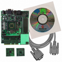
BOARD DEV EXPLORER 16 44-PIN
Manufacturer
Microchip Technology
Series
Explorer 16 44-pinr
Type
MCUr
Datasheet
1.DM240002.pdf
(42 pages)
Specifications of DM240002
Contents
Explorer 16 Dev Board, PIC24FJ64GA004 and dsPIC33FJ32GP204 PIM Modules
Processor To Be Evaluated
PIC24FJ128GA010, dsPIC33FJ256GP710
Processor Series
PIC 24, dsPIC33
Data Bus Width
32 bit
Interface Type
RS-232
Silicon Manufacturer
Microchip
Core Architecture
PIC, DsPIC
Core Sub-architecture
PIC24, DsPIC33
Silicon Core Number
PIC24F, DsPIC33F
Lead Free Status / RoHS Status
Lead free / RoHS Compliant
For Use With/related Products
dsPIC30, dsPIC33, PIC32, PIC24FJ, PIC24HJ
Lead Free Status / Rohs Status
Lead free / RoHS Compliant
Available stocks
Company
Part Number
Manufacturer
Quantity
Price
Company:

Part Number:
DM240002
Manufacturer:
Microchip Technology
Quantity:
135
Company:
Part Number:
DM240002
Manufacturer:
MICROCHIP
Quantity:
12 000


44-Pin Demo Board User’s Guide
DS41296B-page 14
3.2.1
The first lesson shows how to turn on a LED. This is the PIC
of “Hello World” and discusses the I/O pin structures.
New Instructions
The LEDs are connected to I/O pins RD0 through RD7. When one of these I/O pins
drives high, the LED turns on. The I/O pins can be configured for input or output. On
start-up, the default is input. The TRIS Special Function Register bits use the conven-
tion of ‘0’ for output and ‘1’ for input. We want digital output so these must be
configured.
EXAMPLE 3-1:
Now lets look at the program that makes this happen.
; PICkit 2 Lesson 1 - "Hello World"
;
#include <p16F887.inc>
Start:
;
#include
__Config
Org 0
BCF TRISC,0
BSF PORTD,0
GOTO $
BSF
BCF
org 0
BSF
BCF
BCF
BSF
GOTO
END
__CONFIG
__CONFIG
Lesson 1: Hello World (Light a LED)
STATUS,RP0
TRISD,0
STATUS,RP0
PORTD,0
$
Bit set
Bit clear
PICKIT 2, LESSON 1: “HELLO WORLD”
Starts a comment. Any text on the line following the semicolon
Brings in an include file defining all the Special Function Regis-
Defines the Configuration Word. The labels are defined in the
Tells the assembler where to start generating code. Code may
Tells the processor to clear a bit in a file register. TRISD is the
Tells the processor to set pin 0 of PORTD. This will force the I/O
Tells the processor to go to the current instruction.
_BOR_OFF & _CPD_OFF & _CP_OFF & _MCLRE_OFF &
_PWRTE_ON & _WDT_OFF & _INTRC_OSC_NOCLKOUT
_CONFIG2, _WRT_OFF & _BOR21V
_CONFIG1, _LVP_OFF & _FCMEN_OFF & _IESO_OFF &
is ignored.
ters available on the PIC16F887. Also, it defines valid memory
areas. These definitions match the names used in the device
data sheet.
p16F887.inc file. The labels may be logically ANDed
together to form the word.
be generated for any area of the part. Mid-range PIC
controller devices start at address ‘0’, also called the Reset
vector.
tri-state register for pin 0 of PORTD. A ‘1’ in the register makes
the pin an input; a ‘0’ makes it an output. We want to make it an
output, so the bit must be cleared.
pin to a high condition turning on the LED.
; select Register Bank 1
; make IO Pin RD0 an output
; back to Register Bank 0
; turn on LED RD0 (DS0)
; wait here
© 2007 Microchip Technology Inc.
®
microcontroller version
®
micro-
Related parts for DM240002
Image
Part Number
Description
Manufacturer
Datasheet
Request
R

Part Number:
Description:
Manufacturer:
Microchip Technology Inc.
Datasheet:
Part Number:
Description:
Manufacturer:
Microchip Technology Inc.
Datasheet:
Part Number:
Description:
Manufacturer:
Microchip Technology Inc.
Datasheet:
Part Number:
Description:
Manufacturer:
Microchip Technology Inc.
Datasheet:
Part Number:
Description:
Manufacturer:
Microchip Technology Inc.
Datasheet:
Part Number:
Description:
Manufacturer:
Microchip Technology Inc.
Datasheet:
Part Number:
Description:
Manufacturer:
Microchip Technology Inc.
Datasheet:
Part Number:
Description:
Manufacturer:
Microchip Technology Inc.
Datasheet: