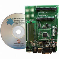
DM183032 Microchip Technology, DM183032 Datasheet - Page 32

DM183032
Manufacturer Part Number
DM183032
Description
BOARD EXPLORER PICDEM PIC18
Manufacturer
Microchip Technology
Series
MPLAB®r
Type
MCUr
Datasheet
1.DM183032.pdf
(38 pages)
Specifications of DM183032
Contents
Evaluation Board
Processor To Be Evaluated
PIC 18
Data Bus Width
8 bit
Interface Type
RS-232, USB
Silicon Manufacturer
Microchip
Core Architecture
PIC
Core Sub-architecture
PIC18
Silicon Core Number
PIC18F
Silicon Family Name
PIC18F8xxx, PIC18FxxJxx
Lead Free Status / RoHS Status
Lead free / RoHS Compliant
For Use With/related Products
PIC18 Series
Lead Free Status / Rohs Status
Lead free / RoHS Compliant
Available stocks
Company
Part Number
Manufacturer
Quantity
Price
Company:
Part Number:
DM183032
Manufacturer:
Microchip Technology
Quantity:
135
Company:
Part Number:
DM183032
Manufacturer:
MICROCHIP
Quantity:
12 000
PICDEM™ PIC18 Explorer Demonstration Board User’s Guide
DS51721B-page 28
A.1.5
The following switches are available:
• S1 – Active-low switch connected to RB0
• S2 – Active-low switch connected to RA5
• S3 – MCLR to hard reset the processor
• S4 – MCLR select switch.
A.1.6
The main oscillator uses a 10 MHz crystal (Y1) which serves as the controller’s primary
oscillator. A second circuit, using a 32.768-kHz (watch type) crystal (Y2), functions as
the Timer1 oscillator, the source for the Real-Time Clock/Calendar (RTCC) and
secondary oscillator.
The PIC18LF2450, the heart of the RS-232 to USB conversion, is independently
clocked with its own 12 MHz crystal (Y3).
A.1.7
A 10 kΩ potentiometer is connected through a series resistor to AN0. To provide an
analog input to one of the controller’s Analog-to-Digital (A/D) channels, the
potentiometer can be adjusted from V
A.1.8
Microchip’s low-cost, in-circuit debugger, MPLAB ICD 2, can be connected to the
modular connector (J10). The ICD connector utilizes RB6 and RB7 for in-circuit
debugging.
A.1.9
Microchip’s low-cost programmer, PICkit 2, can be connected to the 6-pin interface
provided by J12.
A.1.10
The analog thermal sensor, MCP9701A (U1), is used for monitoring temperature. The
device is connected to the Analog-to-Digital Converter (A/D) module through RA1.
A.1.11
A 25LC256, 256 Kbit (32K x 8) serial EEPROM (U9) is included for nonvolatile storage
of firmware.
The EEPROM also can demonstrate the operation of the Serial Peripheral Interface
(SPI) bus. The EEPROM is enabled or disabled from the SPI bus by jumper JP2.
A.1.12
The PICtail™ interface enables the PICDEM PIC18 Explorer Demonstration Board to
be connected directly to available PICtail daughter board cards. This provides a
one-to-one connection between the microcontrollers and the cards through SPI/I
interfaces.
If the on board, PIC18F8722 microcontroller is being used, set this to PIC MCU.
If an alternate, PIM-mounted microcontroller is being used, set this to ICE.
Note:
Note:
Oscillator Options
Analog Input (Potentiometer)
ICD Connector
PICkit™ 2 Connector
Temperature Sensor
Serial EEPROM
PICtail™ Daughter Board Connector
For details, see Section 2.4.1 “Programming Requirements”.
For details, see Section 2.4.1 “Programming Requirements”.
Switches
DD
to GND.
© 2008 Microchip Technology Inc.
2
C™


