DM183032 Microchip Technology, DM183032 Datasheet - Page 19
DM183032
Manufacturer Part Number
DM183032
Description
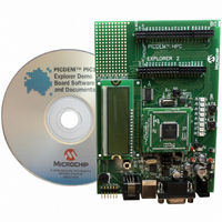
BOARD EXPLORER PICDEM PIC18
Manufacturer
Microchip Technology
Series
MPLAB®r
Type
MCUr
Datasheet
1.DM183032.pdf
(38 pages)
Specifications of DM183032
Contents
Evaluation Board
Processor To Be Evaluated
PIC 18
Data Bus Width
8 bit
Interface Type
RS-232, USB
Silicon Manufacturer
Microchip
Core Architecture
PIC
Core Sub-architecture
PIC18
Silicon Core Number
PIC18F
Silicon Family Name
PIC18F8xxx, PIC18FxxJxx
Lead Free Status / RoHS Status
Lead free / RoHS Compliant
For Use With/related Products
PIC18 Series
Lead Free Status / Rohs Status
Lead free / RoHS Compliant
Available stocks
Company
Part Number
Manufacturer
Quantity
Price
Company:

Part Number:
DM183032
Manufacturer:
Microchip Technology
Quantity:
135
Company:
Part Number:
DM183032
Manufacturer:
MICROCHIP
Quantity:
12 000


© 2008 Microchip Technology Inc.
2.3.3
Other V
populating the PIM board’s R101 and R102 with different value resistors.
A brief overview follows, on how to calculate alternate values for these resistors. For
detailed information, see the LM317 data sheet.
EQUATION 2-1:
I
is the reference voltage developed by the LM317 between the output and adjustment
terminal and equals 1.25V.
That produces the equations shown in Equation 2-2.
EQUATION 2-2:
As stated previously, R25 = 1 kΩ, and R26 = 330Ω. Without R102 and R101 being
inserted in parallel on the PIM board, V
To calculate a desired V
1. Solve for R2, given R1 = R26 = 330Ω.
2. Now knowing R2 and R25, solve for R102.
3. Determine the nearest available resistor value for R102 and recalculate the
Table 2-2 shows the R101 and R102 resistor values to use for different V
table assumes that the PICDEM PIC18 Explorer Demonstration Board’s R25 and R26
resistors are left at their default values of 1KΩ and 330Ω, respectively.
TABLE 2-2:
ADJ
resulting V
will be using.
is minimized by the LM317, so it can be assumed to be zero, or very small. V
† This table assumes that the
DD
R25 and R26 resistors are left at their default values of 1 kΩ and 330Ω,
respectively.
Calculating Other V
values can be produced by the LM317 adjustable voltage regulator by
3.6V
3.3V
3.0V
V
5V
DD
DD
CALCULATING R101, R102 VALUES FOR V
to make sure it does not exceed the maximum V
CALCULATING OUTPUT VOLTAGE
REGULATOR VOLTAGE OUTPUT
OUT
V
R2
R1
OUT
:
=
=
=
V
R25 R102
R26 R101
DD
OUT
V
REF
PICDEM PIC18 Explorer Demonstration Board
||
||
Values
R101 Value
=
OUT
⎛
⎝
1
1.25V 1
Open
Open
Open
Open
+
R2
------ -
R1
=1.25V(1+ 1 kΩ/330Ω) = 5.04V.
=
=
⎛
⎝
⎞
⎠
--------------------------------- -
(
--------------------------------- -
(
(
(
R25
R26
+
R25 R102
R26 R101
+
I
ADJ
R2
------ -
R1
+
+
⋅
⋅
⎞
⎠
R102
R101
⋅
R2
Getting Started
)
)
)
)
DD
DD
OUTPUTS
R102 Value
1.62 kΩ
1.18 kΩ
866 RΩ
for the part you
Open
DS51721B-page 15
DD
values. The
†
REF
’s
Related parts for DM183032
Image
Part Number
Description
Manufacturer
Datasheet
Request
R

Part Number:
Description:
Manufacturer:
Microchip Technology Inc.
Datasheet:
Part Number:
Description:
Manufacturer:
Microchip Technology Inc.
Datasheet:
Part Number:
Description:
Manufacturer:
Microchip Technology Inc.
Datasheet:
Part Number:
Description:
Manufacturer:
Microchip Technology Inc.
Datasheet:
Part Number:
Description:
Manufacturer:
Microchip Technology Inc.
Datasheet:
Part Number:
Description:
Manufacturer:
Microchip Technology Inc.
Datasheet:
Part Number:
Description:
Manufacturer:
Microchip Technology Inc.
Datasheet:
Part Number:
Description:
Manufacturer:
Microchip Technology Inc.
Datasheet: