AS5040 AB austriamicrosystems, AS5040 AB Datasheet - Page 9
AS5040 AB
Manufacturer Part Number
AS5040 AB
Description
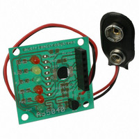
BOARD ADAPTER AS5040
Manufacturer
austriamicrosystems
Specifications of AS5040 AB
Sensor Type
Magnetic, Rotary Position
Sensing Range
360°
Interface
Serial
Voltage - Supply
9V
Embedded
No
Utilized Ic / Part
AS5040
Lead Free Status / RoHS Status
Lead free by exemption / RoHS compliant by exemption
Sensitivity
-


AS5040 10-BIT PROGRAMMABLE MAGNETIC ROTARY ENCODER
Adapter PCB Operation Manual
9.1
The AS5040 Adapter PCB is intended as a standalone device that allows easy and quick testing of the AS5040
without the need of having to make your own PCB. It allows access to each IC pin via a standard 100mil pitch,
600mil Dual-In-Line connector, has LEDs on all digital outputs and comes with an onboard 5V linear voltage
regulator (78L05) and a battery clip to supply the board from a 9V battery.
The 7-pin female connector is designed to fit directly onto the AS5040 Demoboard and use the Adapter PCB as
external encoder (software setting: Encoder = external).
The demoboard however, runs at 3.3V supply voltage. The Adapter PCB is configured for 5V supply voltage.
Connecting both boards without modifications will not harm any of the boards, but may lead to data transmission
errors due to the different digital levels, especially when an extension cable is used between demoboard and
Adapter PCB.
Figure 9: configuring the Adapter PCB for 3.3V operation
Revision A.03 04. Jul.06
* If longer cables are used, a pull-down resistor at the DO line of 22k - 56k Ohms is recommended to discharge
10n
Cap only required for
OTP programming
1
2
3
4
5
6
7
8
Connecting the AS5040 adapter PCB to the demoboard
MagDECn
B_Dir_V
NC
Index_W
VSS
Prog
MagINCn
A_LSB_U
AS5040
IC1
PWM_LSB
VDD3V3
VDD5V
CSn
CLK
DO
the signal between data transmissions and no static voltage is built up.
NC
NC
16
15
14
13
12
11
10
9
Figure 10: Connecting an external AS5040 application to the demoboard
1µF
+
max. length = 2 inches (5cm)
as short as possible!
keep these 6 wires
For programming,
www.austriamicrosystems.com
*see Text
22k
If you use the Adapter PCB as external encoder for the
AS5040 demoboard with an extension cable or
experience data transmission errors, it is recommended
to configure the Adapter PCB for 3.3V supply voltage.
Perform the following modifications:
7
6
5
4
3
2
1
disconnect the 5V supply between Demoboard and
Adapter PCB: remove or cut off pin "+5VUSB" at the
bottom of the AS5040 demoboard
connect pins "3V3" and "5V" on the Adapter PCB.
Ideally, connect the pins right at the bottom of the
7pin female connector with a piece of wire or solder
joint.
you may also remove the 78L05 voltage regulator
from the Adapter PCB to prevent accidental damage
of the IC when an input voltage is applied to the
regulator (and the 5V output is fed to the VDD3V3
supply pin)
PROG
CSN
DO
CLK
VDD3V3
5VUSB
VSS
AS5040 Demoboard
GND
µC
3
2
1
connect to USB
interface on PC
7.5 … 8.0V
only required for
OTP programming
VPROG
VSS
+
10µF
Page 9 of 14
GND
Related parts for AS5040 AB
Image
Part Number
Description
Manufacturer
Datasheet
Request
R

Part Number:
Description:
IC ENCODER PROG 10-BIT 16-SSOP
Manufacturer:
austriamicrosystems
Datasheet:

Part Number:
Description:
BOARD DEMO AS5040
Manufacturer:
austriamicrosystems
Datasheet:

Part Number:
Description:
BOARD PROGRAM AS5040
Manufacturer:
austriamicrosystems
Datasheet:
Part Number:
Description:
IC ENCODER PROG 10-BIT 16-SSOP
Manufacturer:
austriamicrosystems
Datasheet:
Part Number:
Description:
10-bit Programmable Magnetic Rotary Encoder
Manufacturer:
austriamicrosystems
Datasheet:
Part Number:
Description:
IC SWITCH QUAD SPST 14-TSSOP
Manufacturer:
austriamicrosystems
Datasheet:
Part Number:
Description:
IC SWITCH QUAD SPST 14-TSSOP
Manufacturer:
austriamicrosystems
Datasheet:
Part Number:
Description:
IC AMP AUDIO MONO 1.8W 10-MSOP
Manufacturer:
austriamicrosystems
Datasheet:
Part Number:
Description:
IC AMP AUDIO MONO 1.8W 10-MSOP
Manufacturer:
austriamicrosystems
Datasheet:
Part Number:
Description:
IC AMP AUDIO MONO 1.8W 10-MSOP
Manufacturer:
austriamicrosystems
Datasheet:
Part Number:
Description:
IC AMP AUD 1.8W 3DB GAIN 10-MSOP
Manufacturer:
austriamicrosystems
Datasheet:
Part Number:
Description:
IC DRIVER LED 8-DIGIT 24-SOIC
Manufacturer:
austriamicrosystems
Datasheet:
Part Number:
Description:
IC DRIVER LED 8-DIGIT 24-SOIC
Manufacturer:
austriamicrosystems
Datasheet:
Part Number:
Description:
IC, LINE/SPEAKER PHONE CIRCUIT, SOIC-28
Manufacturer:
austriamicrosystems
Datasheet:
Part Number:
Description:
IC MULTI-STANDARD CMOS TELEPHONE SOIC-28
Manufacturer:
austriamicrosystems
Datasheet: