AS5040 AB austriamicrosystems, AS5040 AB Datasheet - Page 2
AS5040 AB
Manufacturer Part Number
AS5040 AB
Description
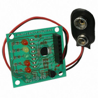
BOARD ADAPTER AS5040
Manufacturer
austriamicrosystems
Specifications of AS5040 AB
Sensor Type
Magnetic, Rotary Position
Sensing Range
360°
Interface
Serial
Voltage - Supply
9V
Embedded
No
Utilized Ic / Part
AS5040
Lead Free Status / RoHS Status
Lead free by exemption / RoHS compliant by exemption
Sensitivity
-


AS5040 10-BIT PROGRAMMABLE MAGNETIC ROTARY ENCODER
Adapter PCB Operation Manual
2 General Description
The AS5040 is a system-on-chip, combining
integrated Hall elements, analog front end and
digital signal processing in a single device. It
provides incremental output signals and the
absolute angular position of a magnet that is placed
either above or below the device.
The AS5040 can be configured to specific customer
requirements by programming the integrated OTP
(one time programmable) register. An internal
voltage regulator allows the AS5040 to operate at
either 3.3 V or 5 V supplies.
3 Pin Configuration
Revision A.03 04. Jul.06
MagDECn
MagINCn
Figure 2: Typical arrangement AS5040 and magnet
A_LSB_U
Index_W
B_Dir_V
VSS
Prog
NC
Figure 3: Pin configuration SSOP16
1
3
4
6
2
5
7
8
16
15
14
13
12
10
11
9
VDD5V
NC
VDD3V3
NC
PWM_LSB
CSn
CLK
DO
www.austriamicrosystems.com
4 Pin Description
Pin
1
2
3
4
5
6
7
8
9
10
11
12
13
14
15
16
Symbol
MagINCn
MagDECn
A_LSB_U
B_Dir_V
NC
Index_ W
VSS
Prog
DO
CLK
CSn
PWM_LSB
NC
NC
VDD3V3
VDD5V
Table 1: Pin description
Type
DO_OD
DO_OD
DO
DO
-
DO
S
DI_PD
DO_T
DI,
ST
DI_PU,
ST
DO
-
-
S
S
Description
Magnet Field Magnitude
INCrease; active low, indicates a
distance reduction between the
magnet and the device surface.
Magnet Field Magnitude
DECrease; active low, indicates
a distance increase between the
device and the magnet.
Mode1: Quadrature A channel
Mode2: Least Significant Bit
Mode3: U signal (phase1)
Mode1: Quadrature B channel
quarter period shift to channel A.
Mode2: Direction of Rotation
Mode3: V signal (phase2)
must be left unconnected
Mode1 and Mode2 : Index
signal indicates the absolute
zero position
Mode3: W signal (phase3)
Negative Supply Voltage (GND)
Programming and Data Input for
Mode configuration, incremental
resolution setting, Zero-Position
Programming and Daisy Chain
mode configuration. Internal pull-
down resistor (~74kΩ)
Data Output of
Synchronous Serial Interface
Clock Input of
Synchronous Serial Interface;
Schmitt-Trigger input
Chip Select, active low; Schmitt-
Trigger input, internal pull-up
resistor (~50kΩ)
Pulse Width Modulation of
approx. 1kHz; LSB in Mode3
must be left unconnected
must be left unconnected
3V-Regulator Output
Positive Supply Voltage 5 V
Page 2 of 14
Related parts for AS5040 AB
Image
Part Number
Description
Manufacturer
Datasheet
Request
R

Part Number:
Description:
IC ENCODER PROG 10-BIT 16-SSOP
Manufacturer:
austriamicrosystems
Datasheet:

Part Number:
Description:
BOARD DEMO AS5040
Manufacturer:
austriamicrosystems
Datasheet:

Part Number:
Description:
BOARD PROGRAM AS5040
Manufacturer:
austriamicrosystems
Datasheet:
Part Number:
Description:
IC ENCODER PROG 10-BIT 16-SSOP
Manufacturer:
austriamicrosystems
Datasheet:
Part Number:
Description:
10-bit Programmable Magnetic Rotary Encoder
Manufacturer:
austriamicrosystems
Datasheet:
Part Number:
Description:
IC SWITCH QUAD SPST 14-TSSOP
Manufacturer:
austriamicrosystems
Datasheet:
Part Number:
Description:
IC SWITCH QUAD SPST 14-TSSOP
Manufacturer:
austriamicrosystems
Datasheet:
Part Number:
Description:
IC AMP AUDIO MONO 1.8W 10-MSOP
Manufacturer:
austriamicrosystems
Datasheet:
Part Number:
Description:
IC AMP AUDIO MONO 1.8W 10-MSOP
Manufacturer:
austriamicrosystems
Datasheet:
Part Number:
Description:
IC AMP AUDIO MONO 1.8W 10-MSOP
Manufacturer:
austriamicrosystems
Datasheet:
Part Number:
Description:
IC AMP AUD 1.8W 3DB GAIN 10-MSOP
Manufacturer:
austriamicrosystems
Datasheet:
Part Number:
Description:
IC DRIVER LED 8-DIGIT 24-SOIC
Manufacturer:
austriamicrosystems
Datasheet:
Part Number:
Description:
IC DRIVER LED 8-DIGIT 24-SOIC
Manufacturer:
austriamicrosystems
Datasheet:
Part Number:
Description:
IC, LINE/SPEAKER PHONE CIRCUIT, SOIC-28
Manufacturer:
austriamicrosystems
Datasheet:
Part Number:
Description:
IC MULTI-STANDARD CMOS TELEPHONE SOIC-28
Manufacturer:
austriamicrosystems
Datasheet: