DM183026-2 Microchip Technology, DM183026-2 Datasheet - Page 39
DM183026-2
Manufacturer Part Number
DM183026-2
Description
KIT EVAL MTOUCH CAPACTIVIE
Manufacturer
Microchip Technology
Series
mTouch™r
Datasheet
1.DM183026-2.pdf
(54 pages)
Specifications of DM183026-2
Sensor Type
Touch, Capacitive
Sensing Range
8 & 12 Buttons/Keys, 2 Sliders
Interface
I²C
Voltage - Supply
5V, USB
Embedded
Yes
Utilized Ic / Part
PIC16F, PIC18F, PIC24F, PIC32MX
Interface Type
USB, I2C, UART
Operating Voltage
5 V
Data Bus Width
32 bit
Silicon Manufacturer
Microchip
Kit Application Type
Sensing - Touch / Proximity
Application Sub Type
Capacitive Touch
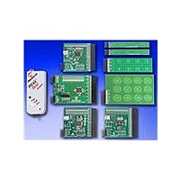
Kit Contents
8x Brds, Serial Anaylizer, USB Cable
For Use With/related Products
PIC16F, PIC24F, PIC18F, PIC32
Lead Free Status / RoHS Status
Lead free / RoHS Compliant
Sensitivity
-
Lead Free Status / Rohs Status
Lead free / RoHS Compliant
Available stocks
Company
Part Number
Manufacturer
Quantity
Price
Company:

Part Number:
DM183026-2
Manufacturer:
Microchip Technology
Quantity:
135
Company:
Part Number:
DM183026-2
Manufacturer:
MICROCHIP
Quantity:
12 000


FIGURE 4-10:
© 2010 Microchip Technology Inc.
Plug-in
Boards
4.3.2
To interface the plug-in boards to the evaluation boards in the mTouch Advanced
Capacitive Evaluation Kits:
1. Connect the evaluation board to the MPLAB
2. Connect the USB receptacle from the workstation to connector J5 of the
3. Connect any of the 4 plug-in boards to the evaluation board through the J4/J3
4. After the hardware connections are done, open the working project in the MPLAB
5. Download the Hex file onto the evaluation board using the MPLAB ICD 3
6. Check the working of the respective plug-in boards and view their output through
EVALUATION BOARD BLOCK DIAGRAM (PIC18F, PIC24F and PIC32MX ONLY)
Note:
Note:
the ICSP connector, J1.
evaluation board. This is also used to power-up the evaluation board. For the
CTMU boards, it is also used to interface to the PC.
connector (48-pin).
IDE and make the required changes for the corresponding plug-in board, which
are explained in the Readme.txt file. However, the default values of the
channel settings of the corresponding header files are mentioned in
Section 2.2 “Individual Touch Sense Demonstrations”. The default settings
of the configured channels are also explained in the Readme.txt file.
interface.
the 16 LEDs on the evaluation board.
J4/J3
PIC18F CTMU, PIC24F CTMU, and PIC32MX CVD Evaluation
Boards with USB Communications
The number of plug-in boards that can be interfaced with the evaluation
board simultaneously is limited by the number of channels in the evaluation
board. Please refer to the specific evaluation board schematic in Appendix
A. “Evaluation Board Schematics” to verify the number of channels
available.
The number of plug-in boards that can be interfaced with the evaluation
board simultaneously is limited by the number of channels in the evaluation
board. In the case of the PIC24F CTMU eval board, the ICD interface (PGD
and PGC) shares two of the input channels of the connector, J4/J3 (channel
6 and channel 7), the operation might fail if any of the plug-in boards is
connected to these 2 channels when the Debugger mode is enabled in the
MPLAB
EVALUATION
BOARD
®
IDE.
J5
J1
Connector
Evaluation Board Hardware
ICSP™
A to mini-B USB Cable
MPLAB
REAL ICE™
EMULATOR
IN-CIRCUIT
®
®
ICD programmer interface through
ICD 3
Cable
USB
Workstation
DS41385C-page 39
Related parts for DM183026-2
Image
Part Number
Description
Manufacturer
Datasheet
Request
R

Part Number:
Description:
Manufacturer:
Microchip Technology Inc.
Datasheet:
Part Number:
Description:
Manufacturer:
Microchip Technology Inc.
Datasheet:
Part Number:
Description:
Manufacturer:
Microchip Technology Inc.
Datasheet:
Part Number:
Description:
Manufacturer:
Microchip Technology Inc.
Datasheet:
Part Number:
Description:
Manufacturer:
Microchip Technology Inc.
Datasheet:
Part Number:
Description:
Manufacturer:
Microchip Technology Inc.
Datasheet:
Part Number:
Description:
Manufacturer:
Microchip Technology Inc.
Datasheet:
Part Number:
Description:
Manufacturer:
Microchip Technology Inc.
Datasheet: